

Results 81 to 90 of 327
-
10-24-2010, 05:49 PM #81150+ Forum Groupie

- Join Date
- Apr 2008
- Location
- Graham, WA
- Posts
- 296
Re: Question about collimated display systems.
It was fun and educational.

I'm sure we'll get it sorted - it's pretty much down to a mechanical process right now.
g.
-
10-24-2010, 06:37 PM #8275+ Posting Member
- Join Date
- Jun 2010
- Location
- Colorado
- Posts
- 131
Re: Question about collimated display systems.
@Mike
Nice diagrams! Not being an optics guy, I'm puzzling over your comment regards the single viewer position and image distortion as you turn your head.
My understanding of a collimated display is that the image viewed is irrespective of position and the sight line from the "lookers eye" to the frame edge of the cockpit window describes the boundaries of the FOV. The image will not "change" if I move from the left seat to the right or get up and walk to the cabin door, just that portion of the image that I see.
If that is true then the purpose of your directions is only to establish a point of reference from which to start the design for mirror/screen geometry and relative placement. Is that correct? And distortion is a property of the projection system, lenses, warping software, geometry tolerances, and other artifacts when moving from the theoretical world to reality.
Perhaps should have asked via PM, but hopefully others will gain from this discussion.
JW
-
10-24-2010, 07:12 PM #83300+ Forum Addict

- Join Date
- Feb 2007
- Location
- California, USA
- Posts
- 377
Re: Question about collimated display systems.
Collimation with a spherical mirror is good, but not perfect.
If the viewpoint is directly under the mirror center of curvature, looking left or right makes no difference. The vertical cross section through the viewer, mirror and screen is the same regardless of lateral viewing angle.
However, if the viewpoint has been shifted forward, perhaps to allow greater vertical field of view (or sideways to fit in a copilot), the vertical cross section including the viewer, mirror and screen is skewed when the viewer looks to the side. The optical paths are longer and the angles different. So, collimation is probably less accurate, and the image is more distorted.
Optimizing a wide-angle collimated display is a tradeoff between many factors.
-
10-25-2010, 11:42 AM #8475+ Posting Member
- Join Date
- Jun 2010
- Location
- Colorado
- Posts
- 131
Re: Question about collimated display systems.
@wledzian
Wasn't quite sure of your question regards numbers in the formula. Could you provide a bit of clarification?
JW
-
10-25-2010, 12:01 PM #85150+ Forum Groupie
- Join Date
- Apr 2010
- Location
- Auburn, WA
- Posts
- 197
Re: Question about collimated display systems.
The 45 is obviously 45 degrees. Is that vertical or horizontal? Originally Posted by castle

I'm assuming that 72 is inches, equal to 6 feet.
What do the other values represent?
-
10-25-2010, 02:47 PM #8675+ Posting Member
- Join Date
- Jun 2010
- Location
- Colorado
- Posts
- 131
Re: Question about collimated display systems.
The 45 is the vertical and 72 is the radius of curvature ( 6 feet ). Originally Posted by wledzian
57.2957 is a radian. A constant used to convert degrees of arc to a linear value. Circumference of a circle is pi*diameter.
or 360 degrees = 3.1415 * 2 * radius
rearranging terms 360 / ( 6.28304 = radius or
the distance along the circumference of a circle equal to the radius is 57.29703 degrees of arc.
By the same token 180 degrees horizontal for a 6 foot radius requires 18.849 linear feet of mylar material (180/57.2957)*6
As you noted, this would be slightly off for something of a flattened arc and does not include the margin required to fastened the mylar to the surface.
JW
-
10-25-2010, 03:50 PM #87300+ Forum Addict
- Join Date
- Feb 2007
- Location
- California, USA
- Posts
- 377
Re: Question about collimated display systems.
The material when flat takes the shape of a truncated cone which has been unrolled. There is significant curvature to the top and bottom edges. The impact is that the width of the required flat rectangular stock is much wider than the vertical chord of the mirror surface.
One very quickly runs up against limits of available material width.
-
10-25-2010, 05:45 PM #88150+ Forum Groupie
- Join Date
- Apr 2010
- Location
- Auburn, WA
- Posts
- 197
Re: Question about collimated display systems.
@Mike.Powell, (cc)geneb:
One challenge Gene and I ran into was the vertical pre-stretch required simply to fit an unrolled cone to the 60° frame. We also tried using the vertical arclength instead of the chord; this fit the frame a bit easier, but would still require more horizontal stretching near the mid-lattitudes than is available by cutting across the horizontal chord. Something considered but not yet tried due to lack of time on Saturday was introducing an arc to the vertical edges to take up some of this gap. Even if we can eliminate some of the prestretch by this method, I'm still concerned that the uneven strain in the horizontal direction combined with near zero strain in the vertical direction will prevent the formation of a spherical surface.
In your research, have you come across any mention of ways to mitigate these issues during mirror fitting?
-
10-25-2010, 06:48 PM #89300+ Forum Addict
- Join Date
- Feb 2007
- Location
- California, USA
- Posts
- 377
Re: Question about collimated display systems.
There are a few methods mentioned.
The horizontal arc of the framework can be extended with the vertical side made straight so no vertical stretch is required during installation. The extended mirror area is useless optically and is masked off.
The vertical framework sides can be made flexible so that the film can be installed with no stretch. The sides are cranked into a curve after film installation.
Temporary, straight frame extensions can be fastened to the frame for film installation. Once the film is vacuum stretched into shape, the vertical sides of the film are clamped to the curved frame sides, the film is trimmed, and the extensions are removed.
The frame sides can be extended with circular arcs which are on a plane which blends with the unstretched conic section of the film as shown below.
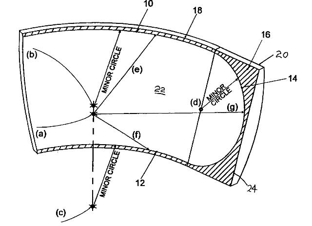
This is from US patent 6050692. I think this has the best chance of success of any hobby approach. It appears to not require stretching during installation, only that the film be pulled taut.
The film tension is not uniformly distributed. I don't think you want it to be. The center horizontal band must stretch the most as it is at the deepest portion of the curve. The top and bottom edges have been cut to the correct length to be on the spherical surface without stretching, so you don't want any horizontal tension there. Vertical tension should be uniform across the whole surface, but of course it won't be at the sides, but the circular arc side additions provide a smooth transition from frame side support to active mirror surface.
I think this produces a satisfactory optical surface as long as the film stays in its elastic region. Once the film stretches beyond its elastic limit, it becomes necessary to prestretch horizontally at the top and bottom. I think this was a major issue in developing film mirrors for displays with vertical fields of view greater than 45 degrees. This probably means that DIY mirrors are limited to 40~45 degree vertical arcs if they are to be one contiguous piece. This may not be an issue due to the limitations on the width of mirror film stock.
-
Post Thanks / Like - 1 Thanks, 0 Likes, 0 Dislikes
 wledzian thanked for this post
-
10-25-2010, 07:05 PM #90Generic GA Sim Builder

- Join Date
- Aug 2009
- Location
- Exeter, Devon, United Kingdom, 1.14701878546E+14, Exeter, Devon
- Posts
- 158
Re: Question about collimated display systems.
Hey guys, umm, sorry to butt in here, ive read parts and im extremely confused, i dont understand this stuff, but, i saw on the Simquip website, that 2 collimating mirrors are for sale, i thought that this may be an appropriate place to mention it, if it hasnt been already
 Heres the link anyway
Simquip Specials Page
Again, im sorry if i missed this before in the post!
Cheers, Jordan

 Reply With Quote
Similar Threads
-
Collimated display build thread...
By geneb in forum Collimated Display DiscussionsReplies: 59Last Post: 07-19-2015, 07:10 PM -
PROS and CONS of LCDs,Collimated,Projector systems ???
By Ross182 in forum General Builder Questions All Aircraft TypesReplies: 0Last Post: 03-04-2010, 09:37 AM -
Looking for measurements and advice for projection display systems.
By mikesblack in forum General Builder Questions All Aircraft TypesReplies: 4Last Post: 01-06-2010, 07:24 PM -
pm SYSTEMS QUESTION
By 767300 in forum PMSystemsReplies: 10Last Post: 01-29-2008, 04:56 AM -
Brainstorming for a collimated mirror display
By s4sha in forum Cockpit Outside VisualizationReplies: 40Last Post: 08-27-2007, 01:33 PM


This radio panel is advertised on Ebay. Does anybody know if I can use it with fs2004 Win7? It...
flightsim radio panel usbc....