

Results 71 to 80 of 327
-
10-22-2010, 09:51 PM #71300+ Forum Addict


- Join Date
- Feb 2007
- Location
- California, USA
- Posts
- 377
Re: Question about collimated display systems.
There are a few other issues to keep in mind as well.
Mylar is elastic, but with a high spring constant. To stretch it, you must pull hard, and it will pull back. With a large mirror, you have a lot of Mylar putting stress on the frame. You need a structure capable of accurately maintaining its shape while supporting perhaps several hundreds pounds force.
Mylar is elastic up to a point then it deforms permanently. If the mirror is too deep, the Mylar must be stretched more and is more likely to be pushed outside its elastic region. When this happens, it won't happen uniformly across the film. Over-stretched Mylar has different properties than Mylar that has not. The distribution of tension across the Mylar is very much not uniform, and the shape is no longer spherical. The optical properties of the mirror are damaged. Much of the recent work on film mirror seems to have been focused on dealing with this.
-
Post Thanks / Like - 1 Thanks, 0 Likes, 0 Dislikes
 wledzian thanked for this post
-
10-22-2010, 10:05 PM #72150+ Forum Groupie
- Join Date
- Apr 2010
- Location
- Auburn, WA
- Posts
- 197
Re: Question about collimated display systems.
That's good info Mike. I'll add a strain estimate to my spreadsheet to display a warning if the strain is outside the elastic region of Mylar's stress/strain curve.
-
10-23-2010, 01:47 AM #7325+ Posting Member
- Join Date
- Sep 2009
- Location
- Eugene Oregon
- Posts
- 60
Re: Question about collimated display systems.
Wow,
That is the most awesome thing you have done. Thank you very much for that. The diagrams are great.
I will need to study the diagrams for a while to get a better understanding and will reply in time.
Also, those patents are most helpful and have provided me with good sense for the construction. I will need to study these further and then will most likely experiment with smaller sections.
Again, most appreciated.
Mike
-
10-23-2010, 09:07 AM #7425+ Posting Member

- Join Date
- Jun 2010
- Location
- swizerland
- Posts
- 42
Re: Question about collimated display systems.
Hi,
didn't see this thread before just now, so I'm still reading through.
I have experimented a lot with plexiglas and mylar to make collimated displays. Some year ago I also made a little beamsplitter visual with a normal plexiglas as beamsplitter and a normal mirror on the backside. That works when it's dark enough in the room. offcourse it will work bether with a real beamsplitter. The best company I found for such mirrors in europe is seco-sign. You can choose how much the mirror should reflect from 5 to approx 20%.
I have also asked several plexiglas specialists here in swizerland if they could form such a spherical shape. The closest I got was one company that makes "bubble-windows" of plexiglass. But they can make max 1m diameters. So to small for a visual. They told me that to make a shape in the magnitude for such a visual plexiglas would be around CHF 20'000.- (that's currently also about $20'000.-) That's just for the form. Mirror coating the formed plexiglas will probalby add another $ 5'000 to 8'000. Each.
So a spherical collimated visual will probably be to expensive or to technical difficult for me. Even just to make the backprojection screen spherical.
What I have started to experiment with some time ago is to make the "collimated" display conical shaped instead of spherical. It's much easier to shape. No heat needed. For the plexiglas mirror and the backprojection screen.
I use an opal white 3mm thik, with 90% light admission as a backprojection screen. The mirror is also 3 mm thik.
http://www.md80.ch/index.php?option=...lator&Itemid=1
This setup is still very experimental. Important is that, this will have a horisontal disortion that needs to be corrected. I use NEC NP901w projectors. They have a software to correct geometry dissortions directly in the projector. So no need for extra CPU consuming software on the pc.
I was wondering, has any one ever asked for prices at those companies like q4services or glassmountain ?
Especially glassmountain always stess their low-costnes. But I guess that very relative. But even if just the backprojection screen would be in a payaple price range would help a lot for a real collimated setup. http://www.glassmountain.com/Simulat...epointDisplays
Cheers,
Gery
-
Post Thanks / Like - 2 Thanks, 0 Likes, 0 Dislikes
-
10-24-2010, 11:49 AM #75150+ Forum Groupie
- Join Date
- Apr 2008
- Location
- Graham, WA
- Posts
- 296
Re: Question about collimated display systems.
wledzian and I got some good work done on Saturday. We're getting closer.

I'm going to try to get the framework I have finished off with interior supports and a sealed back this coming week or so.
g.
-
10-24-2010, 01:50 PM #76150+ Forum Groupie

- Join Date
- Jan 2010
- Location
- London, UK
- Posts
- 205
Re: Question about collimated display systems.
So a non-spherical section mirror with correction does work - or at least provides enough focal distance to trick the eye into seeing through the plane. A conical section mirror like that is easy enough to do with acrylic mirror sheet. Fantastic that someone has already done it! Originally Posted by crashdog

Looks like this may be the way to go with my project - my limited front projection room becomes much less of an issue and I could probably get 140 degrees out of my 16:9 projector.
It'll be fun experimenting
-
10-24-2010, 01:56 PM #7775+ Posting Member
- Join Date
- Jun 2010
- Location
- Colorado
- Posts
- 131
Re: Question about collimated display systems.
56" Mylar would provide a 45 degree FOV for a 6 foot mirror --- (45/57.2957)*72.0 = 56.548
OK, so we're a half inch short but close enough. You can get that size in very large lengths.
A 7 foot system would provide ~ 40 degrees vertical FOV. Still not bad for a DIY and you can't beat the price.
@wledzian. I would like to try and equip my 747 with a six foot mirror. What would you need from me in the way of data to crunch some numbers. Fortunately, have a little more room and a single available stall in my garage shop, but 6.5 radius is the upper limit and 6 leaves a little wiggle room.
Nice work.
JW
-
10-24-2010, 04:09 PM #78300+ Forum Addict
- Join Date
- Feb 2007
- Location
- California, USA
- Posts
- 377
Re: Question about collimated display systems.
Here is a simple graphic approach to designing and analyzing an off-axis collimated display.
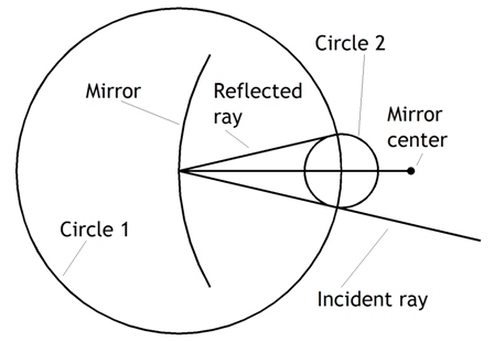
A key step is tracing a ray path as it is reflected by a spherical surface. This draws on some middle school geometry and works well with drawing packages like TurboCAD that have line and circle tools with "snap to intersection" options.
1 - Draw a line from the mirror center to the intersection point of the incident ray with the mirror.
2 - Draw a circle centered on that intersection point. The radius is doesn't matter.
3 - Draw a second circle centered on the intersection of the first circle arc and the line from the mirror center. Set the radius at the intersection between the incident ray and the first circle arc.
4 - Draw the reflected ray from the intersection of the mirror surface and incident ray to the intersection of the arcs of the two circles opposite the incident ray.
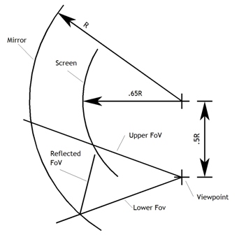
Laying out the positions of the collimating mirror, screen, and viewpoint starts with estimates. Because this is an off-axis system we know that the screen will be larger that the textbook, on-axis figure of half the mirror radius. We'll start with 65% of the mirror radius. We'll place the viewpoint directly under the mirror center of curvature down 50% the mirror radius. The viewpoint doesn't have to be directly under the center, but this position provides the most symmetrical viewing for a single person system, and presumably the smallest geometrical image distortion as you turn your head.
1 - Draw circular arcs representing the mirror and screen surfaces.
2 - Draw lines from the viewpoint representing the upper and lower limits on the vertical field of view.
3 - Reflect the lower field of view up to the screen surface. This is where the lower edge of the screen needs to be for the current estimated position of the viewpoint.
4 - If the screen edge is below the upper field of view limit, the viewpoint is too high. Move the viewpoint lower and try again. If the screen edge is far above the upper limit, move the viewpoint higher and try again. If there is enough space between the lower screen edge and upper FoV limit for the screen framework you haven't designed yet, proceed to step 5.
5 - Reflect the upper FoV limit to the screen. If the reflection misses the screen, the upper FoV may not be possible. Before giving up in dispair, move on to screen placement refinement.
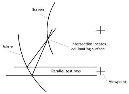
The screen shape and placement is an estimate. Almost certainly you'll want to tweak it. Do this by using parallel test rays that bracket the viewpoint. Reflect them off the mirror to the screen. Their intersection point should be on the screen surface.
1 - Draw two parallel horizontal lines from the viewpoint to the mirror arc. One line should be above the viewpoint, the other below.
2 - Reflect both lines from the mirror. Extend the lines until they intersect.
3 - Draw another pair of parallel lines bracketing the viewpoint to the mirror. These lines should angle downward at the lower FoV limit. Reflect and intersect.
4 - Repeat the process with lines angled at the upper FoV limit.
5 - These three intersection points define a circular arc which is now a very good estimate to where the screen surface should be. The center of this arc is unlikely to be the same as the center of curvature of the mirror. The new screen center will probably be closer to the mirror surface and higher than before. The net effect is to produce a screen that bulges out more and has a top that leans in toward the mirror.
You will probably need to make several passes through the whole process to converge on a configuration that meets your needs.
Once you have a workable configuration, you can ray trace diverging paths from multiple points on the screen surface to check for collimation accuracy.
I used TurboCAD, but I think you can do the same thing with DoubleCAD XT, a free program.
-
10-24-2010, 04:55 PM #79150+ Forum Groupie
- Join Date
- Apr 2010
- Location
- Auburn, WA
- Posts
- 197
Re: Question about collimated display systems.
@castle -
Could you provide a little more info regarding the numbers in that formula? Do you want a wraparound section of a cone? It's the flattening of the conic surface that pushes an otherwise workable mirror height past the available material width. If the conic surface works well, the issue of a monolithic surface may be moot, as joined gores would suffice without introducing issues of distortion due to uneven stress and potential weak points at the seams.
@crashdog -
I'm intrigued by your use of a conic surface mirror and screen. That would certainly be easier to fabricate than a vacuum-formed spherical surface. The horizontal movement of the camera seems to show a distant image, but I'm concerned that the optical properties of a conic surface would introduce significant astigmatism to the image. How does the effect hold up for vertical movement?
@geneb -
Thanks for having me over on Saturday. I have a sense that as many questions were raised as were answered, but it feels like there's some progress. If we can mange to get a mirror formed to your existing frame, it should work well for a 30 degree VFOV with a couple inches margin left over at the top and bottom to take up any residual distortion in the material (3 inch horiz offset, 18 inch vert offset, 75° top angle, 105° bottom angle, convergence at 30 feet). I have a feeling that the following two patents together may offer a solution for mounting the mylar without having to stretch it in the process.
http://www.google.com/patents/about?...BAJ&dq=6050692
http://www.google.com/patents/about?...BAJ&dq=6945659
-
10-24-2010, 05:45 PM #8025+ Posting Member
- Join Date
- Jun 2010
- Location
- swizerland
- Posts
- 42
Re: Question about collimated display systems.
I don't have any math. figures at the moment. The impression I got from my experimental setup is that vertical movement is no problem as long as the angle of the backprojection screen is the same as the angle of the mirror. But the setup has to be dainly precise. Otherweise the picture looks really weird. But I guess the seame issue would be for a spherical setup.
Gery

 Reply With Quote
Similar Threads
-
Collimated display build thread...
By geneb in forum Collimated Display DiscussionsReplies: 59Last Post: 07-19-2015, 07:10 PM -
PROS and CONS of LCDs,Collimated,Projector systems ???
By Ross182 in forum General Builder Questions All Aircraft TypesReplies: 0Last Post: 03-04-2010, 09:37 AM -
Looking for measurements and advice for projection display systems.
By mikesblack in forum General Builder Questions All Aircraft TypesReplies: 4Last Post: 01-06-2010, 07:24 PM -
pm SYSTEMS QUESTION
By 767300 in forum PMSystemsReplies: 10Last Post: 01-29-2008, 04:56 AM -
Brainstorming for a collimated mirror display
By s4sha in forum Cockpit Outside VisualizationReplies: 40Last Post: 08-27-2007, 01:33 PM


This radio panel is advertised on Ebay. Does anybody know if I can use it with fs2004 Win7? It...
flightsim radio panel usbc....