

Results 61 to 70 of 327
-
10-21-2010, 08:24 PM #6125+ Posting Member

- Join Date
- Sep 2009
- Location
- Eugene Oregon
- Posts
- 60
Re: Question about collimated display systems.
Thank you very much indeed. Your help and advice is most appreciated.
The following are the dimensions that I am working with.
Width of sim at widest point(rear) :11 feet.
Measurement from port rear of cockpit to wall: 23 inches.
Measurement from starboard rear of cockpit to wall: 18 inches.
Sim frame slopes in from rear to nose and so the above measurements are the most restrictive.
Height of sim 73 inches at rear and slopes to 57 inches at the apex of the front windows.
Height from top of sim to ceiling is 41 inches at rear.
Length from back of sim to front( measured at apex of front window) 68 inches.
Length from throttle location to apex of front window : 24 inches
and 48 inches to the most forward part of front window.
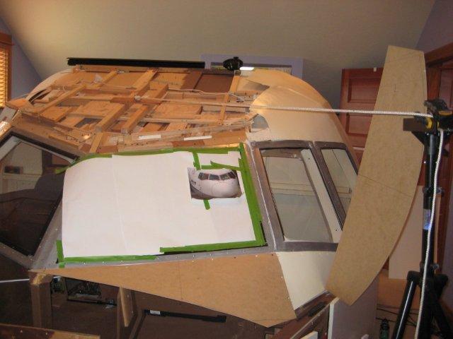
- Note the recent photos I just submitted. There is a rope that is attached to the throttle location and held out at 5 feet. The curve that I have in the photos is 30 degrees and 5 foot radius.
-
10-21-2010, 08:25 PM #6225+ Posting Member
- Join Date
- Sep 2009
- Location
- Eugene Oregon
- Posts
- 60
Re: Question about collimated display systems.
Last edited by Matt Olieman; 10-22-2010 at 07:43 AM.
-
10-22-2010, 12:08 AM #6375+ Posting Member
- Join Date
- Jun 2010
- Location
- Colorado
- Posts
- 131
Re: Question about collimated display systems.
Thought I posted this earlier, but don't see it. Apologies if this winds up as a double post.
In all the discussions on ray tracing and FOV are we actually considering what the pilot will see; i.e., where is the image, amount of distortion, image warping required, and where and how to actually position the mirror and projection screen?
Seems we need to also consider the two rules of reflection for concave mirrors:
Any incident ray traveling parallel to the principal axis on the way to the mirror will pass through the focal point upon reflection.
Any incident ray passing through the focal point on the way to the mirror will travel parallel to the principal axis upon reflection.
In order to do that we also need to specify the principle axis which sets the vertex of the mirror, relative position, orientation, and shape of the object (the screen), and location of the focal point which is on the principle axis at 1/2 the radius.
Need to think about it a bit more....
JW
-
10-22-2010, 01:08 AM #6475+ Posting Member
- Join Date
- Jun 2010
- Location
- Colorado
- Posts
- 131
Re: Question about collimated display systems.
In addition to the FOV another important calculation is the determination of the image formed by the screen and mirror geometry based on their relative positions to each other, the principal axis of the concave mirror that defines the vertex, the focal point, and radius of curvature.
Beat me up and call me crazy, but don't think the examples shown provide that solution. For that we need to apply the two rules of reflection for concave mirrors and incident rays;
* Any incident ray traveling parallel to the principal axis on the way to the mirror will pass through the focal point upon reflection.
* Any incident ray passing through the focal point on the way to the mirror will travel parallel to the principal axis upon reflection.
Performing that calculation(s) will help determine, in addition, the amount of image warping the software has to handle. Also assuming that the principal axis has to intersect the physical mirror and the horizontal axis will be symmetric for the entire 180 degrees and then one only needs to calculate the geometry for a single set of points on the screen in the vertical.
An important item to define is the vertex of the mirror which, in turn, lays out the principal axis and focal point.
This is really neat stuff. Kudos to mikesblack for starting the thread and to all who have contributed.
JW
-
10-22-2010, 01:26 AM #65300+ Forum Addict

- Join Date
- Feb 2007
- Location
- California, USA
- Posts
- 380
Re: Question about collimated display systems.
Film collimating mirrors are spherical-section. Those rules are accurate only for parabolic mirrors or for very shallow spherical mirrors.
-
10-22-2010, 01:37 AM #66150+ Forum Groupie
- Join Date
- Apr 2010
- Location
- Auburn, WA
- Posts
- 197
Re: Question about collimated display systems.
@mikesblack: (Thanks Mike.Powell for the link to the photos) A full-size 767 cockpit - color me green with envy. When I get to work on Monday, I'll pull up the 767 ops manual and check out the eyepoint locations and field of view definitions. I will say that fitting a wide collimated display around that may not be possible in such a tight space. In the meantime, I'll work with guesstimates and see what I can come up with. ...And I haven't forgotten about the patent list.
@Castle: Those two rules only apply to an optical component that actually has a true focal point. A sphere does not have a focal point. While parallel rays very near the axis will converge to a small region around R/2, this does not hold true for rays significantly off-axis. Rather than a focal point, a spherical mirror has a "caustic focal surface". Parallel rays which are close enough together, say the diameter of your pupil, will converge to a small region somewhere along that caustic surface.

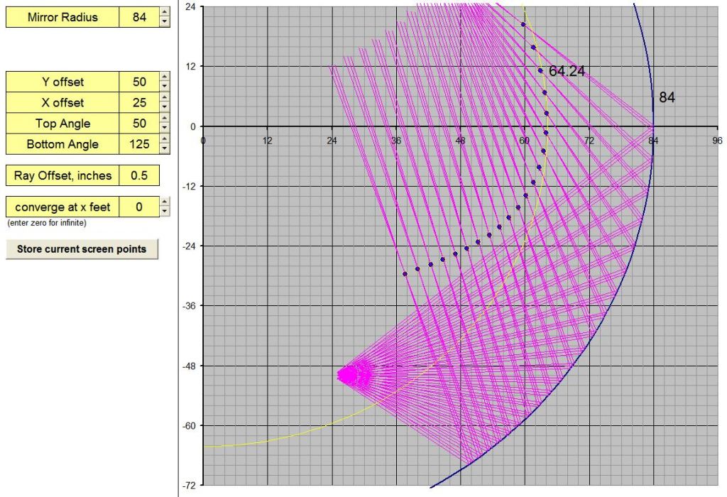
Rather than using the simplifying assumptions of ideal optics, my calculations do in fact calculate the reflected ray vectors for sets of parallel rays (from a hypothetical virtual image at infinity), and calculates the focal point to be the average of their intersections. I can also set a specific image distance for the ray sets so that the cast rays from the eyepoint converge, and generate a focal point for a virtual image at a non-infinite distance. Those calculations are used to generate the points for the limiting surfaces for images at infinity and 30 feet in my earlier post.
-
10-22-2010, 11:19 AM #6775+ Posting Member
- Join Date
- Jun 2010
- Location
- Colorado
- Posts
- 131
Re: Question about collimated display systems.
Dug out my old drafting set and went crazy trying to come up with some diagrams using the aforementioned reflection rules. Nothing seemed to work and what worked wasn't buildable or useful.
So my understanding is you are working from where you want the image to be and then defining the projection screen (location and position) based on the mrror size.
Thank you for the explanation.
JW
-
10-22-2010, 11:45 AM #68150+ Forum Groupie
- Join Date
- Apr 2010
- Location
- Auburn, WA
- Posts
- 197
Re: Question about collimated display systems.
Some of the applicable patents:
Aspheric screen for collimated visual display apparatus
http://www.google.com/patents/about?...BAJ&dq=6944581
Method of constructing a thin film mirror
http://www.google.com/patents/about?...BAJ&dq=6758569
Apparatus for constructing a thin film mirror
http://www.google.com/patents/about?...BAJ&dq=6945659
Collimated visual display with elliptical front projection screen
http://www.google.com/patents/about?...&dq=12/273,053
Method and apparatus for modifying aircraft simulator wide-angle infitiy display equipment mirror to enlarge field of vision and for reskinning aircraft simulator spherical mirror cell to minimize mirror stress and distortion
http://www.google.com/patents/about?...BAJ&dq=7708561
-
Post Thanks / Like - 1 Thanks, 0 Likes, 0 Dislikes
 Matt Olieman thanked for this post
-
10-22-2010, 11:51 AM #69150+ Forum Groupie
- Join Date
- Apr 2010
- Location
- Auburn, WA
- Posts
- 197
Re: Question about collimated display systems.
You're welcome. Originally Posted by castle

I'm doing exactly that, point-by-point, for enough points to sufficiently define the screen shape.
-
10-22-2010, 08:53 PM #70150+ Forum Groupie
- Join Date
- Apr 2010
- Location
- Auburn, WA
- Posts
- 197
Re: Question about collimated display systems.
@Mikesblack:
I took a stab at putting a mirror around your cockpit. I figure you could shoehorn an 84" radius mirror in the space you described, so I started there. I located the eyepoint in a freeware model of a 767 in Sketchup, and set the mirror in place to get a first-shot eyepoint. This first try gives a 180° horizontal FOV and nearly 75 degrees vertical. The mirror geometry intersects the aft windows, so I couldn't swing the HFOV wider.
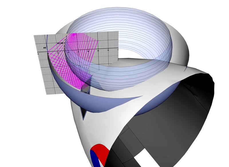
If you're willing to sacrifice some of your vertical FOV (a permanently installed "sunshade" should suffice), you can move the whole mirror assembly aft and get the HFOV to cover all the windows. I haven't worked up the geometry for that yet.
So far, that covers the "is it possible" aspect. There are, however, several large roadblocks:
- The forward structure of the cockpit below the windows interferes with the lower mirror edge. This makes mounting of the mylar challenging.
- The mirror would require a single piece of mylar sheet over 13 feet wide and almost 30 feet long. I haven't been able to find a supplier willing to sell me less than a full production roll for sizes over 56" wide.
- The screen itself is over 10 feet wide, posing its own challenges simply finding raw material for forming.
I can play with mirror placement if you'd like, but the long and short of it is that the optics for a jumbo jet simulator are going to be a bit large to fit in a bedroom.

 Reply With Quote
Similar Threads
-
Collimated display build thread...
By geneb in forum Collimated Display DiscussionsReplies: 59Last Post: 07-19-2015, 07:10 PM -
PROS and CONS of LCDs,Collimated,Projector systems ???
By Ross182 in forum General Builder Questions All Aircraft TypesReplies: 0Last Post: 03-04-2010, 09:37 AM -
Looking for measurements and advice for projection display systems.
By mikesblack in forum General Builder Questions All Aircraft TypesReplies: 4Last Post: 01-06-2010, 07:24 PM -
pm SYSTEMS QUESTION
By 767300 in forum PMSystemsReplies: 10Last Post: 01-29-2008, 04:56 AM -
Brainstorming for a collimated mirror display
By s4sha in forum Cockpit Outside VisualizationReplies: 40Last Post: 08-27-2007, 01:33 PM


Candid connections: Platform for casual relationships Live Women Prime Сasual Dating
Super Сasual Dating - Genuine...