

Results 51 to 60 of 327
-
10-21-2010, 12:49 AM #51300+ Forum Addict


- Join Date
- Feb 2007
- Location
- California, USA
- Posts
- 380
Re: Question about collimated display systems.
I've been using TurboCAD to do ray tracing. It's a little cumbersome, but I believe it to be accurate. I'm not using the paraxial approximations. Rather, I trace reflections based on the law of reflection (angle of incidence equals angle of relfection). The idea is that when a ray hits the mirror surface, I draw a line from the mirror center to the point where the ray intersects the mirror. I then draw the reflected ray to match the incident ray angle. It requires a bit of middle school geometry construction, but it appears to work. The results I'm getting are similar to the optical configuration in the 1982 NTIS report "Wide-Angle, Multiviewer, Infinity Display System".
For an off-axis system, the screen surface shifts closer to the mirror with the top tilting even closer. While a vertical cross section through the screen is still a circular arc, its center shifts toward the screen while the vertical axis of revolution stays with the mirror center, so the screen surface becomes toroidial or oblate (slightly squashed)
As far as image distortion goes, I'm hopeful that image warping software like Nthusim will be the solution. A requirement for color-corrected, aspheric projection lenses would make the project impractical.
A possibility is front projecting the screen using a second spherical-section mirror as a fold mirror. Possibly, this would resolve some or most of the projection distortion.
-
10-21-2010, 07:31 AM #52Executive Vice President, MyCockpit

- Join Date
- Oct 2005
- Location
- Ocala, FL USA
- Posts
- 2,884
Re: Question about collimated display systems.
Just some pics you may find interesting:

Matt Olieman

 [/IMG]


Last edited by Matt Olieman; 10-22-2010 at 09:34 AM.
-
Post Thanks / Like - 2 Thanks, 0 Likes, 0 Dislikes
-
10-21-2010, 10:42 AM #53150+ Forum Groupie
- Join Date
- Apr 2010
- Location
- Auburn, WA
- Posts
- 197
Re: Question about collimated display systems.
I don't have a list of the patents handy and time is short at the moment, but I'll pull the list together and post it tonight.
The patents don't give any real insight into the shape of the screen. Most of them state something along the lines of "this invention comprises a rear-projection screen of spherical shape, generally 1/2 the radius of the collimating mirror" or similar. Several patents even go so far as to specify non-spherical shapes (sections of ellipse or toroid), but continue to perpetuate the falsehood of a radius substantially half of the mirror.
I've also put together an Excel spreadsheet to play with geometry. In essence, I cast several sets of parallel rays from a prospective eyepoint, and let Excel do the math to see where each set converges. These points form the shape of the mirror surface. Ponts on this line will be collimated at infinity, at the selected eyepoint. Points on a surface of larger radius will appear to be closer to the pilot. As long as the virtual image is more than 30 feet out, monocular depth cues will dominate.
The shape of the screen is strongly defined by the chosen eyepoint and size of the spherical mirror.
The bottom edge (and therefore lower limit of vertical FOV) is limited by the highest sightline from the eyepoint. This is the limiting factor in the restricted vertical FOV.
The TOP of the screen has no such restrictions, and extending the top of the screen allows the pilot to lean forward and look upward. As long as the cockpit structure has a more restrictive lower vertical limit than the display, the pilot won't see the bottom edge of the mirror, and the illusion will be maintained.
-
Post Thanks / Like - 1 Thanks, 0 Likes, 0 Dislikes
 Matt Olieman thanked for this post
-
10-21-2010, 11:57 AM #5475+ Posting Member
- Join Date
- Jun 2010
- Location
- Colorado
- Posts
- 131
Re: Question about collimated display systems.
Mike,
The image when the object is between the concave mirror and focus is a virtual image formed behind the mirror. Does the program allow you to extend the ray to a point behind the mirror where the image "exists"? Supoose you could do that manually but so much nicer if the program did it.
JW
-
10-21-2010, 01:34 PM #5525+ Posting Member
- Join Date
- Sep 2009
- Location
- Eugene Oregon
- Posts
- 60
Re: Question about collimated display systems.
"I've been reading through several patents related to design, manufacture and installation of cross-cockpit collimated displays. A few things I've learned:
The bottom edge (and therefore lower limit of vertical FOV) is limited by the highest sightline from the eyepoint. This is the limiting factor in the restricted vertical FOV." from wledzian
Thanks again wledzian. I really appreciate your insights in this.
In regard to the mirror's bottom edge, I am trying to figure out the radius to use and also the lower edge location. I want to place the lower edge higher than the sim floor, perhaps a foot or so below the cockpit windows. This would set the bottom of the arc, or bottom of sphere above the cockpit floor. The rational is to have the mirror set close to the sim, as space is an issue in my room, while capturing a full range of view.
I have cut a couple of sections of arc, 5 and 6 feet respectively that are 30 degrees each. I want to get a general idea how much space will be used by placing these cut arcs next to the windows, look outside and make sure I don't see the borders.
Given the examples that I have seen on pro simulators, the mirror edge seems close or at cockpit floor level. I wonder if by raising the sphere vertically as I have described, I would be making the mirror unworkable. Best to know ahead of time before plunging in.
-
10-21-2010, 01:38 PM #5625+ Posting Member
- Join Date
- Sep 2009
- Location
- Eugene Oregon
- Posts
- 60
Re: Question about collimated display systems.
Few interesting links:
Matt,
How can I upload an image (jpeg) here?
Mike
http://www.q4services.com/links.php
http://www.simulation.org.uk/register.php
-
10-21-2010, 02:46 PM #57300+ Forum Addict
- Join Date
- Feb 2007
- Location
- California, USA
- Posts
- 380
Re: Question about collimated display systems.
TurboCAD allows line extension. Select the line and drag as far as you want. TurboCAD also provides a means to measure the angle between two line segments. It draws a circular arc centered on the intersection point even if the segments have not been drawn long enough to intersect. It's a quick and dirty way to see where the image falls, as well as, what the angular collimation error is. Originally Posted by castle

This is undeniably clumsy, but it seems to work. I've been developing graphical techniques for locating the top and bottom edges of the mirror given the field of view requirements and viewpoint location. It also lets me know where the screen should be and what the shape is. I've been using the pro version of TurboCAD, but I expect the free version of DoubleCAD XT would work as well.
OSLO is a professional optical design tool available in a free student version. It's another possibility, but I haven't taken the time to learn how to use it.
-
10-21-2010, 02:48 PM #58150+ Forum Groupie
- Join Date
- Apr 2010
- Location
- Auburn, WA
- Posts
- 197
Re: Question about collimated display systems.
So much to say, so little time during lunch break... Originally Posted by mikesblack
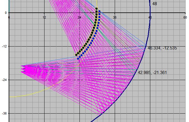
Here's a quick sample from my raycasting simulation.
- The dark blue circular line is the mirror. In this case, radius is 48 inches.
- Magenta lines represent the cast rays. Vertical FOV is 10 deg up, 30 deg down. Eyepoint is located 20 inches below the center, offset 4" forward to represent the offset of my eyes from the vertical rotation axis of my head. For this simulation, I've used a parallel ray offset of 1". Due to the shape of the mirror generated by these parameters, this geometry may not be achievable for a full 180 degree horizontal FOV unless I can find a reasonable source of mylar film in larger widths.
- Black dots represent the screen for convergence at infinity. A screen surface inside these points will not properly form a virtual image when viewed from the design eyepoint.
- Blue dots represent the screen for convergence at 30 feet. A screen surface outside these points will produce a virtual image closer than 30 feet, partially defeating the purpose of collimation.
- The yellow line represents a spherical screen at the minimum radius required to form an image over the full field of view. As you can see, a screen of this shape would further restrict the achievable vertical FOV and would cause the lower half of the image to appear too close. It also serves to illustrate the oblate spheroid nature of the 'proper' screen shape.
The commercial sims typically have a mirror radius between 9 and 11 feet, and have a much larger horizontal offset applied to the design eyepoint. If you provide a bit more information about your sim, I can crunch some numbers for you. Originally Posted by mikesblack
In designing my sim (still in the design phase), I started with the space I could get away with taking up, chose a field of view based on desired over-the-nose visibility in the pattern and on approach, and designed the cockpit interior based on the space remaining. My cockpit will be a single-pilot generic pit, as I'm finding that the bottom edge of the 48" mirror is driving the location of my instrument panel, and would not be usable for a cockpit sized for two pilots.
I won't be home until rather late tonight, I'll get that list of patents put together tomorrow morning.
-
10-21-2010, 03:06 PM #59Executive Vice President, MyCockpit
- Join Date
- Oct 2005
- Location
- Ocala, FL USA
- Posts
- 2,884
Re: Question about collimated display systems.
You can either attach it to your post or what would be better; post it in the Photo Gallery and link the image to it there. When you look at a image in the "Photo Gallery" you'll see near the bottom "Direct link:" That would be the link to your image. Originally Posted by mikesblack
Hope that helps.
Matt Oleiman
-
10-21-2010, 07:07 PM #6025+ Posting Member
- Join Date
- Sep 2009
- Location
- Eugene Oregon
- Posts
- 60
Re: Question about collimated display systems.
Thanks Matt. That does.
By the way, has anyone seen this ?
http://www.doti-optics.com/PERMA%20%C2%AE%20Mirror.htm

 Reply With Quote
Similar Threads
-
Collimated display build thread...
By geneb in forum Collimated Display DiscussionsReplies: 59Last Post: 07-19-2015, 07:10 PM -
PROS and CONS of LCDs,Collimated,Projector systems ???
By Ross182 in forum General Builder Questions All Aircraft TypesReplies: 0Last Post: 03-04-2010, 09:37 AM -
Looking for measurements and advice for projection display systems.
By mikesblack in forum General Builder Questions All Aircraft TypesReplies: 4Last Post: 01-06-2010, 07:24 PM -
pm SYSTEMS QUESTION
By 767300 in forum PMSystemsReplies: 10Last Post: 01-29-2008, 04:56 AM -
Brainstorming for a collimated mirror display
By s4sha in forum Cockpit Outside VisualizationReplies: 40Last Post: 08-27-2007, 01:33 PM


Candid connections: Platform for casual relationships Live Women Prime Сasual Dating
Super Сasual Dating - Genuine...