

Results 11 to 20 of 53
Thread: Interfacing real 727 eng gauges
-
12-19-2009, 09:58 AM #11Executive Vice President, MyCockpit


- Join Date
- Oct 2005
- Location
- Ocala, FL USA
- Posts
- 2,884
Re: Interfacing real 727 eng gauges
Fantastic information Rob..... Thank you

-
12-19-2009, 01:10 PM #12300+ Forum Addict
- Join Date
- Feb 2007
- Location
- California, USA
- Posts
- 380
Re: Interfacing real 727 eng gauges
Okay, at this point we know the gauges are functional, and that they require a signal that swings around 0.
We still need to know the input resistance of the gauge. We can get this by using the test oscillator even though it doesn't trigger the gauge. When the gauge is hooked up to the "B" output, what are the voltages at "B", and at the gauge input?
If the input resistance is not too low we can use a transistor and a few resistors to convert a digital signal to one that swings around 0. If the input resistance is too low, we'll need something a bit more complex.
-
12-19-2009, 02:03 PM #1375+ Posting Member
- Join Date
- Jan 2009
- Location
- Derby, UK
- Posts
- 128
Re: Interfacing real 727 eng gauges
Nice work chaps.
Pity your scope is playing up Rob - Just when you really need it!
Interesting that sine at 30Hz doesn't work.
Cheers,
Rob
-
12-19-2009, 03:08 PM #14500+ This must be a daytime job

- Join Date
- Feb 2006
- Location
- Indianapolis, IN
- Posts
- 761
Re: Interfacing real 727 eng gauges
Ok Mike here you go,
Source V = 6.4V
Output no load = 3.1V 32Hz
A= .4 drop to 2.7V
B= .5 drop to 2.6V
C= .6 drop to 2.5V
-
12-19-2009, 03:09 PM #15500+ This must be a daytime job
- Join Date
- Feb 2006
- Location
- Indianapolis, IN
- Posts
- 761
Re: Interfacing real 727 eng gauges
 Originally Posted by RadarBob

Exactly what i thought! Could be more to it im sure as im no engineer. lol
-
12-20-2009, 06:54 PM #16300+ Forum Addict
- Join Date
- Feb 2007
- Location
- California, USA
- Posts
- 380
Re: Interfacing real 727 eng gauges
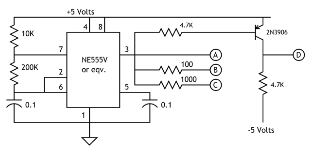
I calculate the tachometer input resistance to be 18,750 Ohms. This is high enough that we should be able to drive the tach with a relatively simple circuit.
[The method of calculating the input resistance isn't difficult, but the description is wordy, so I left it out. However, if there is interest, I would be happy to post it.]
Your success with the audio signal indicates that we will need a signal that crosses over 0 rather than simply pulsing a positive voltage.
As a next step, I'd like to try a modification to the test oscillator. The addition of a transistor and a pair of resistors produces an output signal that bounces between +5 volts and -5 volts.
Connecting the tach input to "D" should result in a mid-scale reading on the gauge.
-
12-28-2009, 09:42 AM #17500+ This must be a daytime job
- Join Date
- Feb 2006
- Location
- Indianapolis, IN
- Posts
- 761
Re: Interfacing real 727 eng gauges
Mike,
It worked! I used a pot in place of the 200K resistor and was able to control the gauge perfectly with your circuit. I added another 555 to get my -5v and 70hz output gave us 100% on the gauge. Now what is our next step?
Thanks,
Rob
-
12-28-2009, 12:36 PM #18300+ Forum Addict
- Join Date
- Feb 2007
- Location
- California, USA
- Posts
- 380
Re: Interfacing real 727 eng gauges
Rob,
There are a number of options. We could hang a microcontroller off the serial com port and have it generate the tach signal. We could perhaps make use of existing interface gear you already have. For example, if you have an interface that produces a 0 to 5 volt output, we could develop a voltage to frequency converter. Do you already have some sort of interface gear?
-
12-28-2009, 12:56 PM #19500+ This must be a daytime job
- Join Date
- Feb 2006
- Location
- Indianapolis, IN
- Posts
- 761
Re: Interfacing real 727 eng gauges
Mike,
I have some opencockpits servo driver boards right now. We would need to convert the pwm signal from that to operate the gauge. That would be the easiest to program for me as I can account for slope and intecept angles of the gauge with that software. The PIC on the serial port interest me as well but i'm not familiar with programming them. I found a very small PWM to analog signal http://www.bpesolutions.com/bpemanua....to.analog.pdf
but nothing for a PWM to frequency. my idea is, if possible ,I would get the boards made by pcbexpress or similar, make it a cat5 style hook-up from the gauge to interface. Thaoughts, comments or other ideas? Also for the record, i am just a hobbiest electronics guy with basic understanding and not an engineer. I do learn quick and self teach myself allot which almost always cost more in both time and money. (in destroyed parts) lol
Thanks,
Rob
-
12-28-2009, 10:01 PM #20300+ Forum Addict
- Join Date
- Feb 2007
- Location
- California, USA
- Posts
- 380
Re: Interfacing real 727 eng gauges
The PIC on a serial port is easy to do. It's an adaptation of the stepping motor gauge tha's posted as a sample chapter. The stepping routine would be replaced with a variable frequency oscillator routine. A transistor would be added similar to the one used on the 555 test oscillator.
However, as you already have the OpenCockpits servo board, I'm toying with a different idea. The thought is to take the variable pulse width RC servo control signal and run it into a dedicated PIC. The PIC measures the pulse width then creates a square wave output at a frequency proportional to the pulse width.

 Reply With Quote
Similar Threads
-
Interfacing a real GPS with FSX?
By Shawn in forum General Builder Questions All Aircraft TypesReplies: 7Last Post: 02-21-2009, 01:39 AM -
Interfacing real radios with SIOC
By sja in forum Interfacing Real Aviation PartsReplies: 6Last Post: 02-12-2009, 10:32 AM -
Interfacing real radios with SIOC
By sja in forum I/O Interfacing Hardware and SoftwareReplies: 6Last Post: 02-12-2009, 10:32 AM -
ideas on interfacing real 737 start switches ?
By dnoize in forum I/O Interfacing Hardware and SoftwareReplies: 5Last Post: 08-20-2008, 08:47 AM -
interfacing real yoke trim switch with IO cards????
By steve diamond in forum I/O Interfacing Hardware and SoftwareReplies: 3Last Post: 08-29-2006, 04:23 PM


Girls in your town
A320 Sound Files Missing