

Results 1 to 10 of 13
Thread: 777 Project Update
-
09-13-2011, 06:01 PM #125+ Posting Member

- Join Date
- Dec 2005
- Location
- USA
- Posts
- 49
777 Project Update
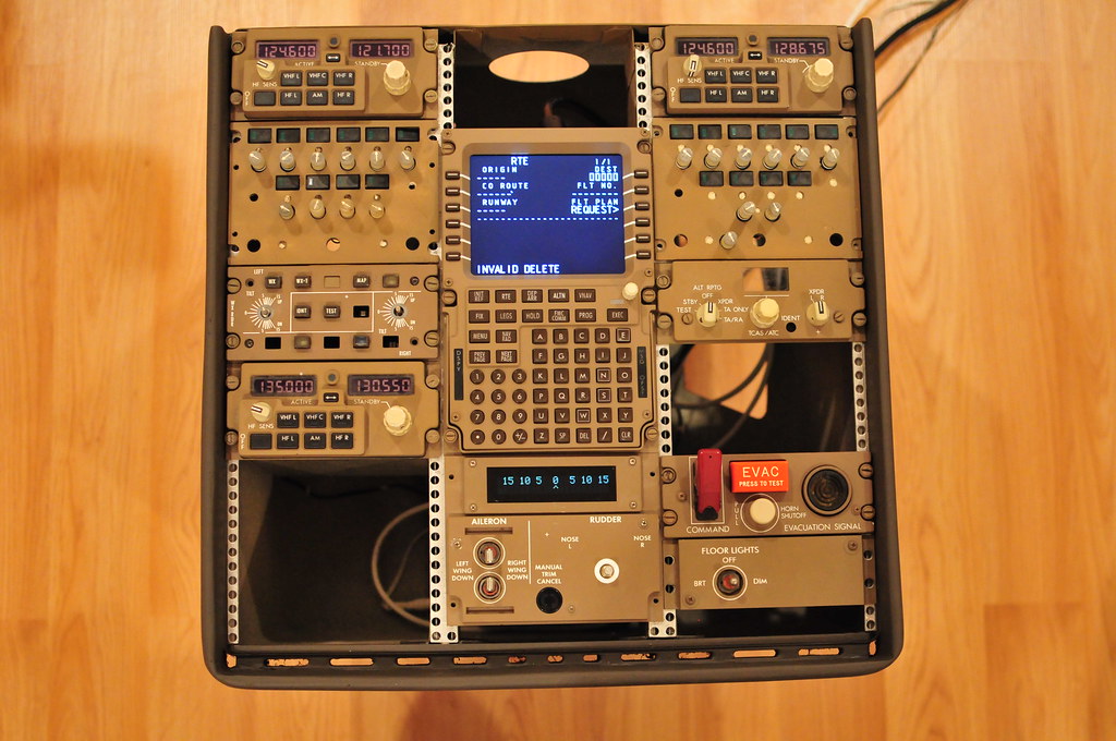
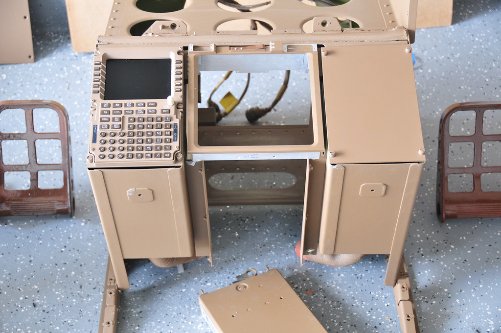
I have added most of the modules to the center pedestal, and almost all the digital components are functional including all three radios, the rudder trim indicator and the CDU. The radios are using the OEM LCDs, the rudder trim indicator is from Phidgets and the CDU is from FDS (Pro-MX). The ACPs will soon be replaced and the fire handles will be installed.

I'll make this a running thread for future updates.Robert Prather
http://777simulator.com
-
Post Thanks / Like - 1 Thanks, 0 Likes, 0 Dislikes
 W9XE/Project777 thanked for this post
-
09-13-2011, 10:20 PM #2150+ Forum Groupie

- Join Date
- Jun 2009
- Location
- California
- Posts
- 220
Re: 777 Project Update
makes me drool! great job!
-fabian
my 757 sim specs
-
09-14-2011, 02:30 PM #3Executive Assistant

- Join Date
- Jul 2007
- Location
- North,East England
- Posts
- 1,445
Re: 777 Project Update
This is brilliant, really nice to see some workmanship with boeing brown aicraft colours.
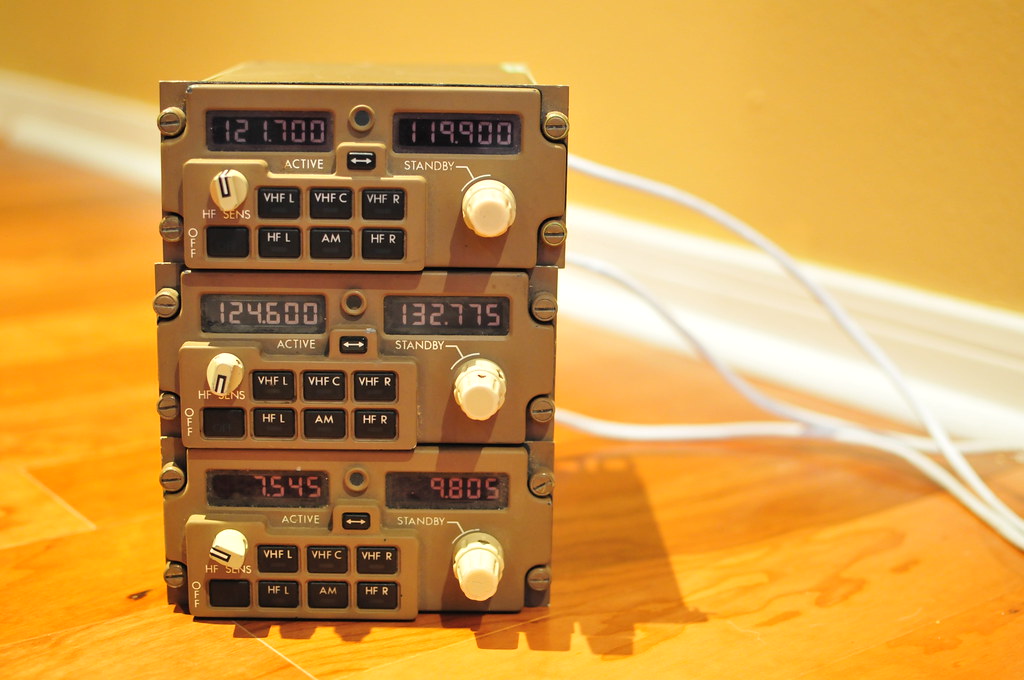
How did you wire the radios! Look great with the original digits.
Please do keep posting photos, fascinating thread, i for one will be keeping a look out!
Best Regards
-
09-14-2011, 04:12 PM #425+ Posting Member
- Join Date
- Dec 2005
- Location
- USA
- Posts
- 49
Re: 777 Project Update
Thank you both very much for your complements!
The brown stuff has been a real challenge, but it's finally coming together. The radios are still a work in progress. They require different combinations of AC and DC voltage to identify radio position (i.e. L/C/R), data modes, offside tuning conflicts, etc. Some are pre-requisites to the unit successfully powering up. The white wires are Cat5e cables, which connect to a control box, which handles power and data distribution. The original unit used cannon plugs, but Cat5 is so much easier to work with I haven't quite figured out how I want to handle the interfacing since FS only supports COMM1/2. I'm sure I'll figure out something for the HF/AM sides.
Robert Prather
http://777simulator.com
-
10-08-2011, 05:43 PM #525+ Posting Member
- Join Date
- Dec 2005
- Location
- USA
- Posts
- 49
Re: 777 Project Update
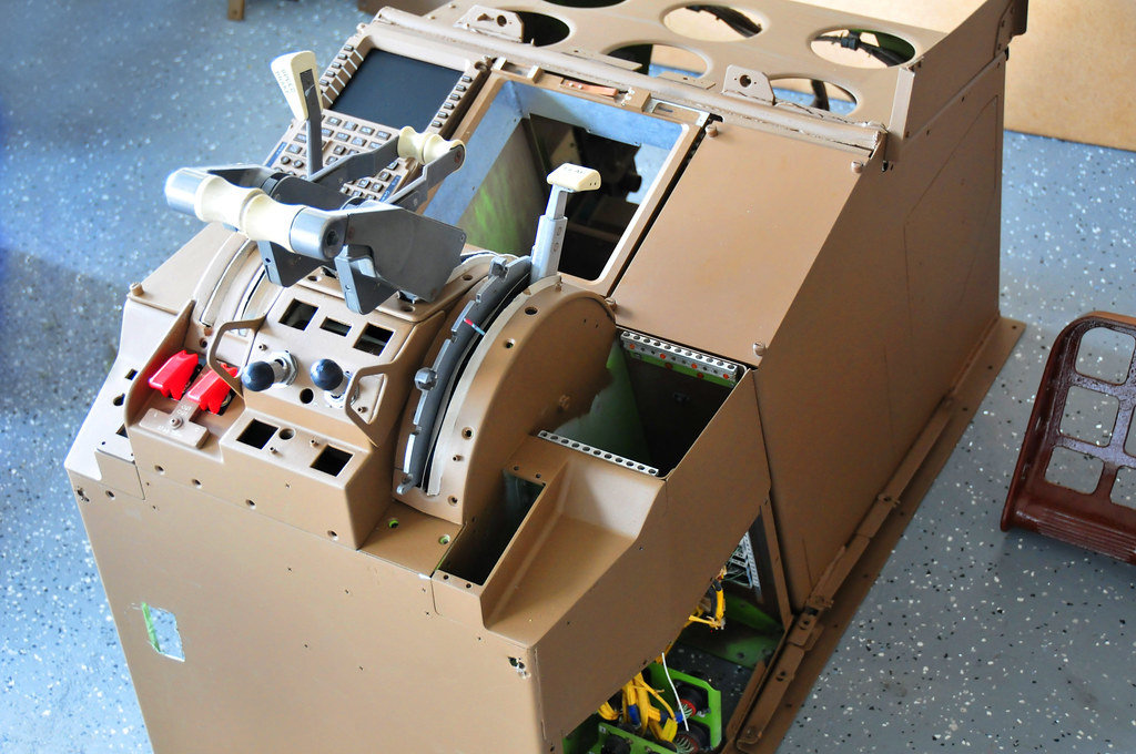
Since my 767 CDU stand doesn't have a lower EICAS, I had to modify it to accommodate the 777 DU frames. There were 6 screws holding it in place, but two were very difficult to turn, so I cut off the back of the screws and the center support popped off. I then notched the aluminum DU frame, and it fit in place great! I'll have to do some more cutting to get the lower EICAS control panel to fit.

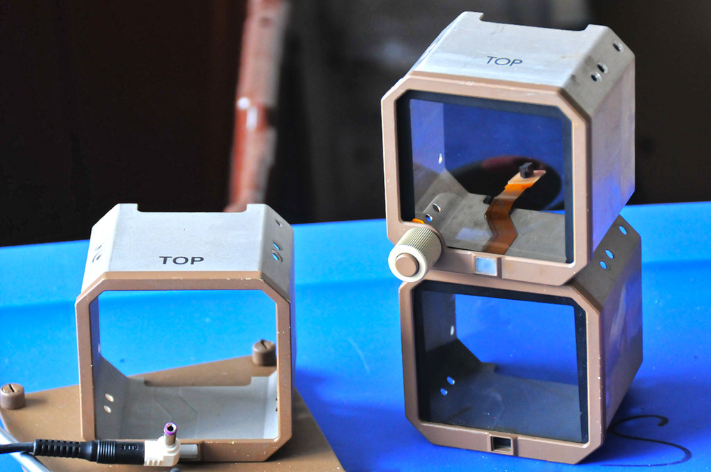
The flat ribbon cable, on the standby instrument, is connected to the rotary knob and the light sensor. The glass is polarized.Robert Prather
http://777simulator.com
-
Post Thanks / Like - 1 Thanks, 0 Likes, 0 Dislikes
W9XE/Project777 thanked for this post
-
11-01-2011, 11:30 PM #625+ Posting Member
- Join Date
- Dec 2005
- Location
- USA
- Posts
- 49
Re: 777 Project Update
I cut an approximately 1/2 inch notch out of the back wall of the CDU stand in order to allow the CDU screen to fit. Until I made the notch deep enough, the screen bezel prevented the throttle quadrant from sliding into place. Now the screen fits great and the back of the frame has been sanded smooth.
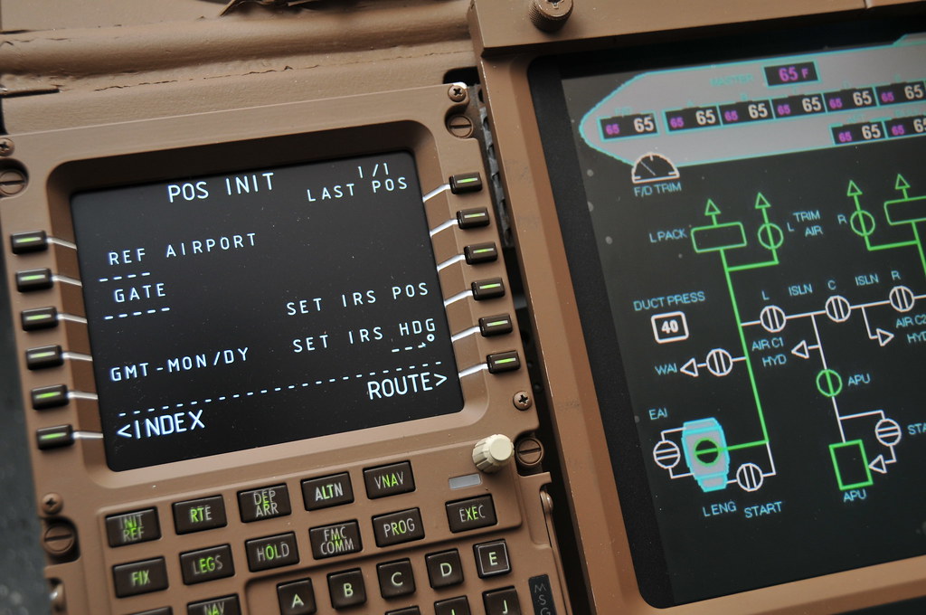
CDU is FDS Pro-MX and Lower EICAS software is Pro MFD 777 Collection.
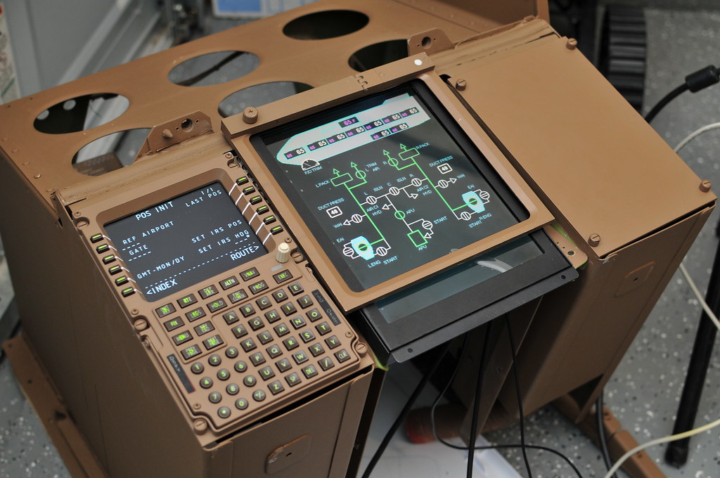
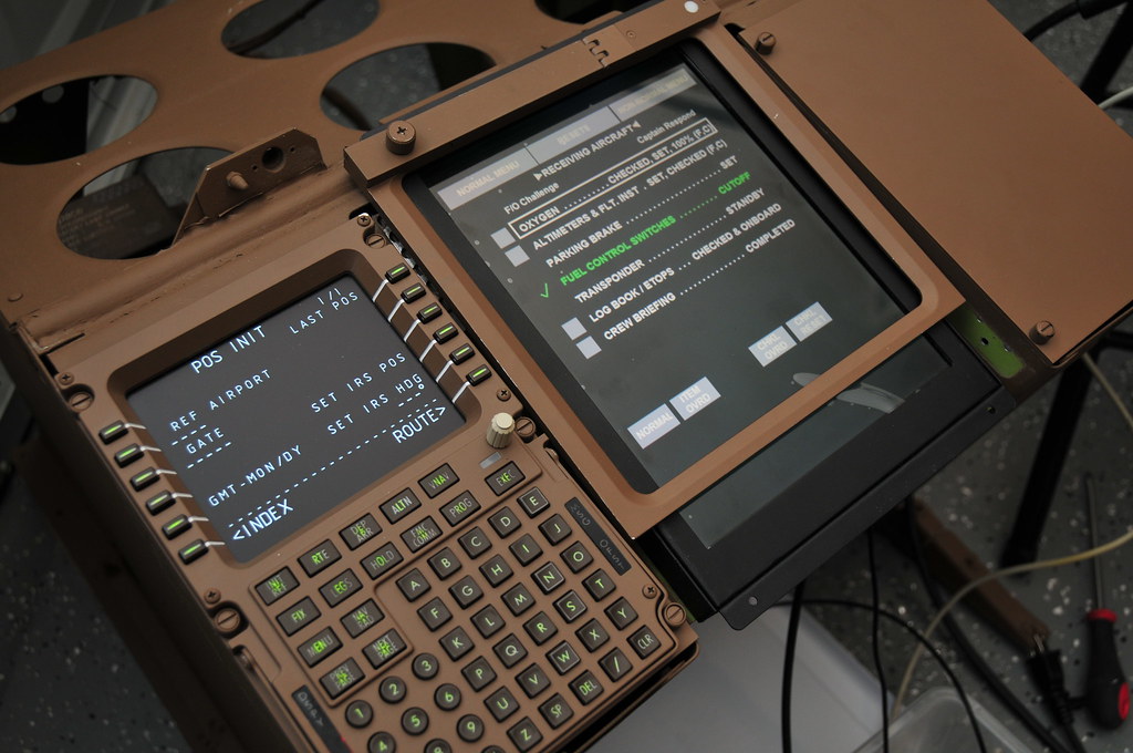
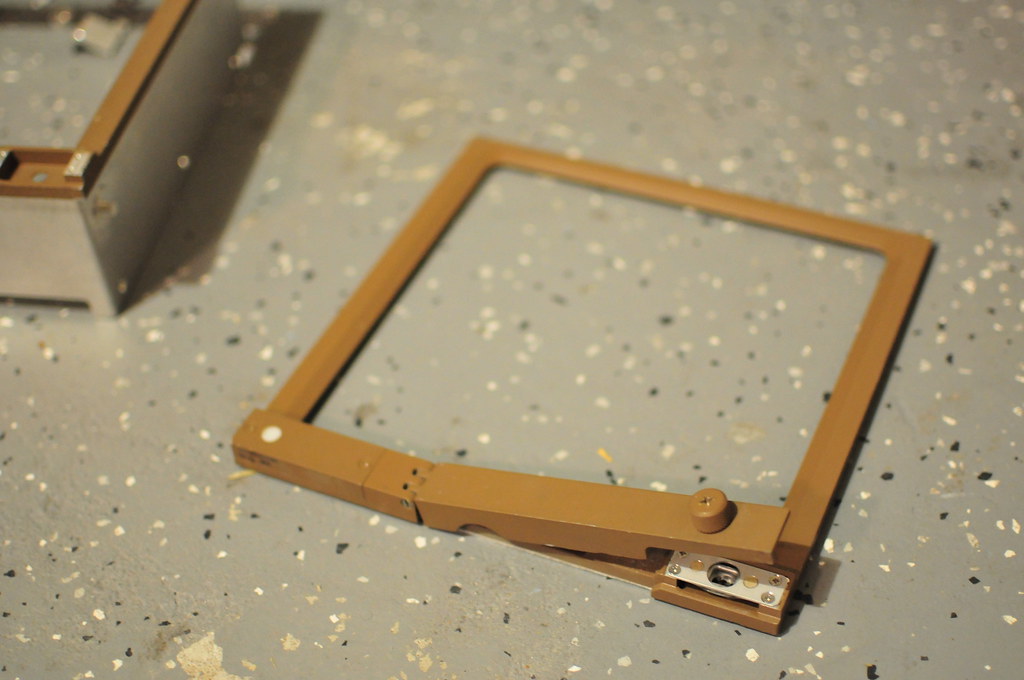
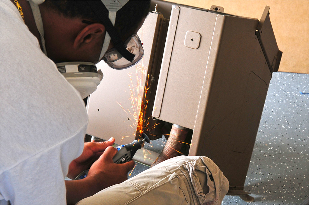
I had to cut the aluminum case off the frame to allow it to sit flush on top of the lower DU.Robert Prather
http://777simulator.com
-
Post Thanks / Like - 1 Thanks, 0 Likes, 0 Dislikes
W9XE/Project777 thanked for this post
-
11-02-2011, 12:21 PM #725+ Posting Member

- Join Date
- Aug 2007
- Location
- South Wales, UK
- Posts
- 61
Re: 777 Project Update
Incredible work Robert. Very neat and tidy setup you have there. The attention to detail is absolutely superb.
Well done.
Rhydian
-
11-02-2011, 05:43 PM #8300+ Forum Addict

- Join Date
- Aug 2008
- Location
- São Paulo, Brazil, Brazil
- Posts
- 306
Re: 777 Project Update
OMG!! Great job!!!
-
11-03-2011, 07:10 PM #925+ Posting Member
- Join Date
- Oct 2010
- Location
- Perth
- Posts
- 52
Re: 777 Project Update
Thats a fantasic effort Robert.
What size lcd did you use for your lower eicas?
It fits very well. This will be my next step.
Tom
-
11-04-2011, 07:01 PM #1025+ Posting Member
- Join Date
- Dec 2005
- Location
- USA
- Posts
- 49
Re: 777 Project Update
Thanks very much for all the kind feedback! The screen is a 10.4" Pyle LCD. I love it! It's completely enclosed with a really thin bezel and a built in VGA cable. You have to buy a separate 12VDC adapter, though that actually works out because the monitor's power input is a red wire and a black wire, making it VERY easy to connect to an interface card, relay or adapter.
http://www.amazon.com/PLVW10IW--Wall...9303949&sr=8-1Robert Prather
http://777simulator.com

 Reply With Quote