

Results 181 to 190 of 327
-
11-25-2010, 12:32 PM #181Our new friend needs to reach 10 posts to get to the next flight level

- Join Date
- Nov 2010
- Location
- Egypt
- Posts
- 8
Re: Question about collimated display systems.
Thank you Matt for your post .. Originally Posted by Matt Olieman

I watched all the videos , but I didn't understand how the vacuum form the Mylar on the frame !!!
but i noticed that the rear-projection screen isn't uniform & a bit distorted .. is this the reason why the picture on the mylar isn't uniform ?? or the reason is that the mylar itself ??
I went to the factory , they can do it .. but the cost made me Deaf !!
Plz tell me the theory of using a vacuum .. ( what it do )
Thanks
-
11-25-2010, 12:37 PM #182Executive Vice President, MyCockpit


- Join Date
- Oct 2005
- Location
- Ocala, FL USA
- Posts
- 2,883
Re: Question about collimated display systems.
@ SU-Medo, The questions you are asking are all answered in this thread. I understand the difficulty with the language barrier, but it's here. Please try to translate using Google translator, perhaps that will help. Originally Posted by SU-Medo
Also read Mike Powell's articles related to collimated displays: HERE
Matt OliemanLast edited by Matt Olieman; 11-25-2010 at 12:39 PM.
-
11-25-2010, 12:57 PM #183150+ Forum Groupie
- Join Date
- Apr 2008
- Location
- Graham, WA
- Posts
- 296
Re: Question about collimated display systems.
Quick summary - The frame forms the outline of a a spherical section and when the mylar is properly placed on the frame and you apply a vacuum source to it, it pulls the mylar into the spherical section shape that the framework "describes".
This is what it looks like as a "solid":
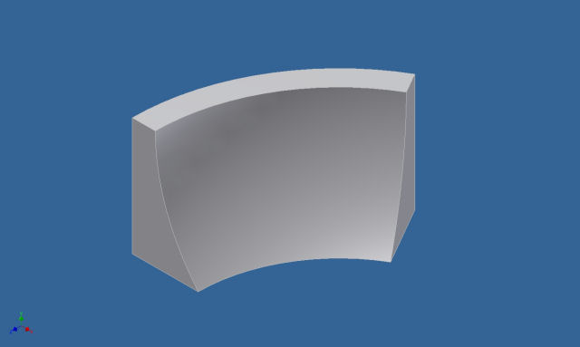
As soon as you turn off the vacuum, the mylar "relaxes" and no longer forms the mirror. This is shown especially well in the first video that Wayne posted that shows the first time we applied vacuum to the mirror.
Also, we're not using rear-projection.
The majority of the weirdness you see in the videos is the result of the kraft-paper wrapped screen. It will get MUCH better when skinned with material that's not doing its level best to fold, crease, wrinkle and tear itself while being wrapped around the screen framework.
g.
-
11-26-2010, 12:57 AM #184Our new friend needs to reach 10 posts to get to the next flight level
- Join Date
- Nov 2010
- Location
- Egypt
- Posts
- 8
Re: Question about collimated display systems.
Matt .. thank you for Mike Powell's articles , I appreciate that for you ..
Thank you so much for the summary , I got it now .. Originally Posted by geneb
Whatever the type of projection ( rear or forward ) , I saw a big ball from white acrylic in a shop , It's used for containing a lamp for lighting in streets .. It was big enough ( by guessing it has a radius about 3' feet ) , I think we can cut a part similar to the curvature of the Mylar mirror's frame to use it as a rear/forward-Projection screen .....
-
11-26-2010, 09:41 AM #185Executive Vice President, MyCockpit
- Join Date
- Oct 2005
- Location
- Ocala, FL USA
- Posts
- 2,883
Re: Question about collimated display systems.
I wondered about using something like SU-Medo mentioned (the acrylic white ball).
Rear projection would still be a preference, well, for me, anyway.....
I've played around with sheets of Lexan, forming shapes. Lexan is easy to form and takes a little heat, it's also easy to repair when scratched. Anyway, I thought about this when I saw the forming of glass video, with lexan it's the same method, but less heat.
Matt Olieman
-
11-26-2010, 05:46 PM #18675+ Posting Member
- Join Date
- Jun 2010
- Location
- Colorado
- Posts
- 131
Re: Question about collimated display systems.
Originally Posted by Matt Olieman
Here is some info on paints for front projection systems you all might find useful for the collimated projection screen or any DIY front projection system for that matter
http://myplace.frontier.com/~vzepdzs...t%20screen.htm
I'll be using it on my 180 wrap around, not collimated but okay for now. Playing with mirrors geometries to shorten throw distances, idea is to bend a surface into shape with something like Lexan then skin it with a one mil mylar sheet to create a FS mirror. The amount of bending is amazingly little in the vertical, radius of curvature on the order of 15 to 17 feet Haven't tried it yet, but with a conventional mylar mirror was able to cold bend it to produce the following mesh pattern shown,, this is with a VERY rough first order mesh distortion program which will be fine tuned and enhanced to handle localized warping as needed and edge blending
JW
-
Post Thanks / Like - 3 Thanks, 0 Likes, 0 Dislikes
-
11-26-2010, 06:33 PM #187150+ Forum Groupie
- Join Date
- Oct 2010
- Location
- Australia
- Posts
- 163
Re: Question about collimated display systems.
Hi, Originally Posted by castle
Here is a link to the use of a curved Sintra sheet and a mirror. The information may be of interest to you if you haven't already seen it.
http://www.biagettis.com/737simproje...roject_008.htm
Kind Regards
Bernie.
-
11-26-2010, 07:22 PM #188300+ Forum Addict
- Join Date
- Feb 2007
- Location
- California, USA
- Posts
- 377
Re: Question about collimated display systems.
Nice work! Originally Posted by castle
-
11-26-2010, 08:31 PM #18975+ Posting Member
- Join Date
- Jun 2010
- Location
- Colorado
- Posts
- 131
Re: Question about collimated display systems.
Yes, I saw that. Thank you. Originally Posted by Bernie
Two aspects of that approach I'm trying to improve on. First, using a curved mirror and screen rather than a flat acrylic provides 180 degree with a screen radius of six feet (~2M) This allows you to increase the FOV in the vertical; important for the side view where the side windows are closer plus by placing the mirrors at the edge of the cabin, you reduce or eliminate the problem where the cabin edge might shadow the reflected image, second FS mirrors to eliminate image ghosting can be expensive in larger sizes and customized curved ones can be very expensive. You can create a FS mirror from a conventional mirror by removing the protective backing. It can be done with some care, but that will be a flat surface.
If using a thin mylar skin stretched on a concave surface works, it opens the door for an effective DIY low cost solution and also one to customize a mirror shape. And then create the appropriate distortion mesh designed for the precise arrangement of cameras, mirrors, and screens.
Cheers
JW
-
11-27-2010, 12:28 AM #190150+ Forum Groupie
- Join Date
- Apr 2008
- Location
- Graham, WA
- Posts
- 296
Re: Question about collimated display systems.
Wayne stopped by for a bit today and we were able to get some "pre-saturday" work done.

These parts....
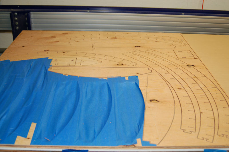
Will combine to build this...
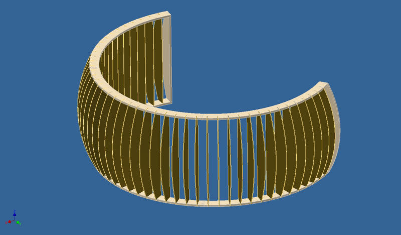
The rendering above is the 225 degree screen for the new mirror. The spaces between the ribs will be filled with 2" insulation foam that's been hot-wire cut to shape. The framework is made from 7/16" plywood and the thin ribs are to be cut from 1/8" hardboard. Not shown in the drawing is the supporting structure that will be on the top & bottom of the screen.
It turns out that my original screen design will work out with 56" wide mylar, so the new mirror will cover a vertical FOV of 40 degrees and right around 220 degrees or so horizontally. The diameter remains the same at 8 feet.
The screen as designed is about 52" or so across at the widest point of the base ring. It's a bit wider than that overall because of the ribs - but not large enough to properly do rear projection using a vacu-formed screen.
More tomorrow!
g.
-
Post Thanks / Like - 1 Thanks, 0 Likes, 0 Dislikes
 Matt Olieman thanked for this post

 Reply With Quote
Similar Threads
-
Collimated display build thread...
By geneb in forum Collimated Display DiscussionsReplies: 59Last Post: 07-19-2015, 07:10 PM -
PROS and CONS of LCDs,Collimated,Projector systems ???
By Ross182 in forum General Builder Questions All Aircraft TypesReplies: 0Last Post: 03-04-2010, 09:37 AM -
Looking for measurements and advice for projection display systems.
By mikesblack in forum General Builder Questions All Aircraft TypesReplies: 4Last Post: 01-06-2010, 07:24 PM -
pm SYSTEMS QUESTION
By 767300 in forum PMSystemsReplies: 10Last Post: 01-29-2008, 04:56 AM -
Brainstorming for a collimated mirror display
By s4sha in forum Cockpit Outside VisualizationReplies: 40Last Post: 08-27-2007, 01:33 PM
