

 Section
 Categories

LED Basics
LEDs are increasingly the light source of choice in electronics. Compared to incandescent lamps, LEDs are cooler, more efficient, often smaller, less expensive, available in different colors, monochromatic without the need of a filter, and last much longer. They function as status/power and alphanumeric indicators, send data across fiber optic cables, backlight monitors and televisions, provide the illumination in some types of avionics light plates, generate room mood lighting, and even replace projector lamps in newer model video projectors. Theres a pretty good chance youll be using LEDs in your sim.
Perhaps the most commonly seen individual LED is a plastic cylinder about a quarter of an inch in diameter and a third of an inch long. Electrons go in (and out) of one end while photons come out the other. The photon end often is shaped as a hemispherical lens. There is actually a very wide variety of LED packages. Surface mount LEDs can be small enough to be a challenge to pick up without tweezers. These work well for back lighting switches and light plates. Their larger cylindrical cousins are made in several sizes. The extended LED family includes rectangular and dome shaped members, as well as, special packages to accommodate the heat produced by the high power clan members. There is almost certainly a LED package to meet your need.
An individual LED produces light over a narrow range of wavelengths that we perceive as a single color. Red was the first color to appear in the consumer market. Its been joined by yellow, orange, green, blue, ultra violet, and infra red. White light LEDs are made by combining multiple, different color LED chips in a single package, or by using a blue or ultra violet LED to excite fluorescent materials in the plastic LED package.
The intensity of LED light output is typically specified in milli-candelas (mc in the catalog listings).A few tens or hundreds of milli-candelas is a bright, direct-view indicator, like a power-on light. Several thousand milli-candelas is quite bright, painfully so if you look directly at the LED. LEDs of this power illuminate light plates and flight/engine instruments. A few of them in a small canister fixture make a nice map light for night time use. Truly high power LEDs have light intensity specified in lumens (Lm). These can cause scarring of the retina if you look directly into the LED hot spot.
LED light may be tightly focused or widely dispersed. Catalogs typically refer to this as the viewing angle. A tightly focused LED is useful for illuminating a legend in a warning panel or push switch. A LED with diffuse, widely dispersed light might be used for a direct view indicator. High intensity LEDs with large viewing angles are used for edge lighting applications like avionics light plates.
The viewing angle is determined by the shape and material of the package and the position of the LED chip within the package. Focused LED packages are made of optically clear material and tend to have hemispherical ends that function as lenses. A flat end will result in a wider viewing angle. A dimpled end will push the majority of the light out the side. Using diffuse rather than clear material for the body will also broaden the viewing angle.
We live in a voltage-powered world. (Not me personally, Im powered by caffeine and salty, fatty foods.) We plug our computers in to wall outlets that supply 120 or 220 volts, depending on country. Looking inside electronic appliances we find chips powered by 12, 5, or 3.3 volts. Were conditioned by our experience to power everything from a voltage.
But LEDs are different.
LEDs prefer to be powered by a regulated current supply. Yes, you can power a LED directly from a voltage source, but its problematic. Small changes in voltage result in large changes in LED performance. Catastrophe lurks around the corner. This is all because as voltage supplied to a LED is increased, the current through it goes up exponentially. As we crank up the voltage from zero we see: no light, no light, a little light, whoa Bright, then SMOKE. None of this happens when we power the LED from a controlled electrical current.
But thats too much trouble, so we fake it by putting a resistor in series with the LED and using a voltage supply anyway.
The trick is to choose the correct resistor.
The first step is to choose the desired current through the LED. Most small individual LEDs operate well at 20 milliamps. We arent required to operate at this level, however. If we wanted more or less light, we could change this as long as we stay within the particular LED maximum ratings. In this case well stick with 20 milliamps.
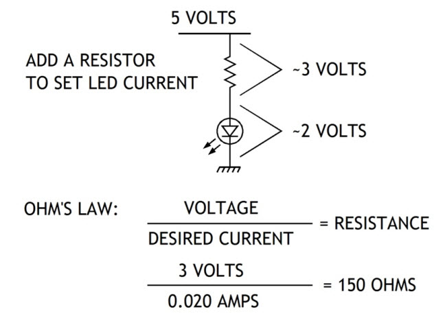
Now we take note of the supply voltage. Lets assume in this example that the LED is a power indicator on a micro controller logic board running on 5 volts, so well be running this LED from the boards 5 volt supply.
When a LED makes photons there is a voltage across it called the forward voltage (Vf in spec sheets). Its different for each type of LED, but for most it ranges between 1.7 and 2.4, though for blue LEDs it tends to be closer to 4 volts. Lets go with 2 volts.
The resistor-LED series combination is connected to 5 volts. Since the LED has 2 volts across it, the resistor must have 3 volts across it. (Its just that simple!)
Ohms law says voltage (in volts) across a resistance (in ohms) equals the current (in amps) through it times the resistance value. Well flip that around to calculate the value of our resistor: resistance value equals the voltage across the resistor divided by the current through it. Three volts divided by 0.020 amps equals 150 Ohms. (20 milliamps is the same as 0.020 amps.)
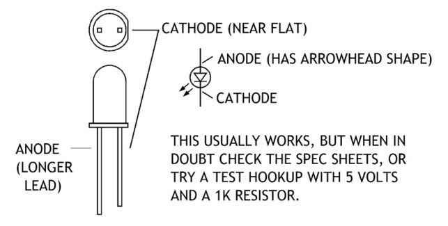
The only tricky part is figuring out how to orient the LED when connecting it. A LED is, after all, a Light Emitting Diode, and diodes conduct in only one direction (mostly). One lead of the LED connects to its anode; the other lead connects to its cathode. For the LED to operate the anode voltage must be more positive than the voltage on the cathode.
The symbol for a LED is basically a diode symbol, a triangular arrowhead pointing to a bar. The arrowhead is the anode. The bar is the cathode. (Mnemonic: the anode points to the cathode.)
Determining which lead is which when you hold the LED in your hand can be confusing. Often the anode lead is longer, and the LED body has a flat spot nearer the cathode lead. If theres any question, check the manufacturers spec sheet or try a test hook-up with a 1K resistor and 5 volts.
You can generally find basic information about specific LED models on the catalog pages of the distributors supplying LEDs which includes just about every electronic parts supplier. Jameco (www.jameco.com), Digikey (www.digikey.com), Mouser (www.mouser.com), etc. They are also popular items on Ebay.
Look on the manufacturers websites for more comprehensive information. Everlight (www.everlight.com), Ledtech (www.ledtech.com), Lite-on Electronics (www.liteon.com), Avago Technologies (www.avagotech.com), and MCD Electronics (www.mcdelectronics.com).
Mike Powell, author of
Building Recreational Flight Simulators and
Building Simulated Aircraft Instrumentation.
www.mikesflightdeckbooks.com