

Results 11 to 20 of 26
Thread: Vulcan Bomber...
-
10-27-2011, 03:43 PM #1175+ Posting Member


- Join Date
- Mar 2010
- Location
- Netherlands
- Posts
- 131
Re: Vulcan Bomber...
The seat of 25000 dollars was that the chrome one?
It should be possible to buy a semi comlpete one for a lot less, if you can find one..... I think we bought our seat for around 500 pounds, 25 years or so ago.
The seat you are building looks very good! If you need close up pictures just mail me and i will take some and mail them to you. It might take a day or to for me to react because i am not always able to mail .
Best regards, Remco
-
Post Thanks / Like - 1 Thanks, 0 Likes, 0 Dislikes
 matthew73 thanked for this post
-
11-02-2011, 03:13 AM #1210+ Posting Member
- Join Date
- Aug 2011
- Location
- Australia
- Posts
- 16
Re: Vulcan Bomber...
Hi folks. Here are some pics of the progress on my Martin Baker Mk3KS ejection seat.
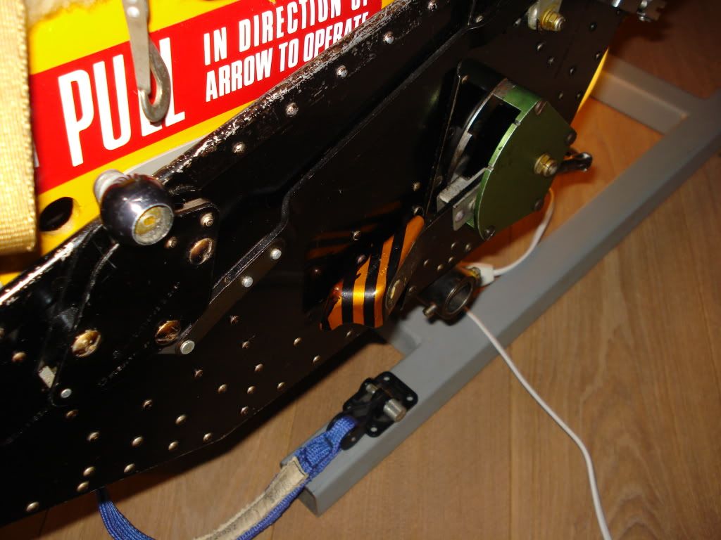
The first and second image is of the older style "harness release, manual overide handle". Its made of 3mm alluminium flat bar, and a slab of MDF for the grip. It will have lovely black and yellow stripes on its upper half. The third image is of what i believe are called the "leg restraint line snubbing units". Made from MDF and pine. One end of the "leg restraint lines" attach onto its lowest, front position. As far as i know, the snubbing units hold the leg restraint lines in position, then release them upon fireing of the seat, they reel inwards to pull the legs of the victim, err, i meen the aviator, so that he does not leave his kneecaps behind on the lower edge of the instrument panel of the aircraft. REMCOSOL! I will need some help on their position please? ( in next post ). The fourth image is of some strapping that i bought at my local market for $15 bucks total. The green one will be for the parachute lift lines, and leg loops. The sand colored one will be for the parachute restraining straps, and for the wedge pad restraining straps. The fith image is of the leg restraint lines, which is elastic tie down strap. It mounts at one end to a unit thats under the seat. Im trying to determine exactly how they mount at the bottom front of the snubbing units. I just cant find a diagram or large, clear image of it with the lines insitu.
Im now starting to explore the inner workings of FSX airplane models and stuff to learn how to build my sim. And other aspects of cockpit building and Fsx interfaceing. So at the moment, this project is just like building a full size plastic scale model at home. And the cockpit is sometimes the most fun part to build in a kit. Cheers.
Photo592.jpgPhoto595.jpgPhoto597.jpgPhoto598.jpgPhoto600.jpg
-
11-02-2011, 03:38 AM #1310+ Posting Member
- Join Date
- Aug 2011
- Location
- Australia
- Posts
- 16
Re: Vulcan Bomber...
Hi REMCOSOL. Hope you are doing well. Can i have some help with my leg restraint lines please? I have been studying diagrams and many photos on the web to determine the placement of the leg restraint lines. Many of the images of these seats are either from museams, private collections, decommisioned A/C and restored cockpits. Its hard to find an image of a complete seat with the details i want.
In the third image in the post below. You see the leg restraint line snubbing units with pilot hols drilled in the bottom front section. Could you please tell me how the restraint line attaches to it. Does the line thread into the unit, or does it attach via a clip, link, shackle, etc?
Your seat is the most complete one that i have seen outside of an aircraft. As far as you know, are your leg restraint lines placed correctly ? ( i.e. factory ). Could you please describe their position and attachment to the seat and them buckles. Yes, the crome/polished seat was the $25,000 modern art master piece. No takers yet.
Any help, from anyone, greatly appreciated. Thanks, and take it easy.
-
11-02-2011, 05:51 AM #1475+ Posting Member
- Join Date
- Mar 2010
- Location
- Netherlands
- Posts
- 131
Re: Vulcan Bomber...
Hi!
I Will make Some pictures today and post them here. Somewhere ive got the original drawings of the seat I'll try to find them because I can remember that the legrestraints were crossconnected on that. Most pictures show them the way I've connected them now.
Your seats are looking very nice keep up the good work!
Best regards Remco
-
11-02-2011, 07:05 AM #1575+ Posting Member
- Join Date
- Mar 2010
- Location
- Netherlands
- Posts
- 131
Re: Vulcan Bomber...
Hi Matthew,
Here are some pictures:
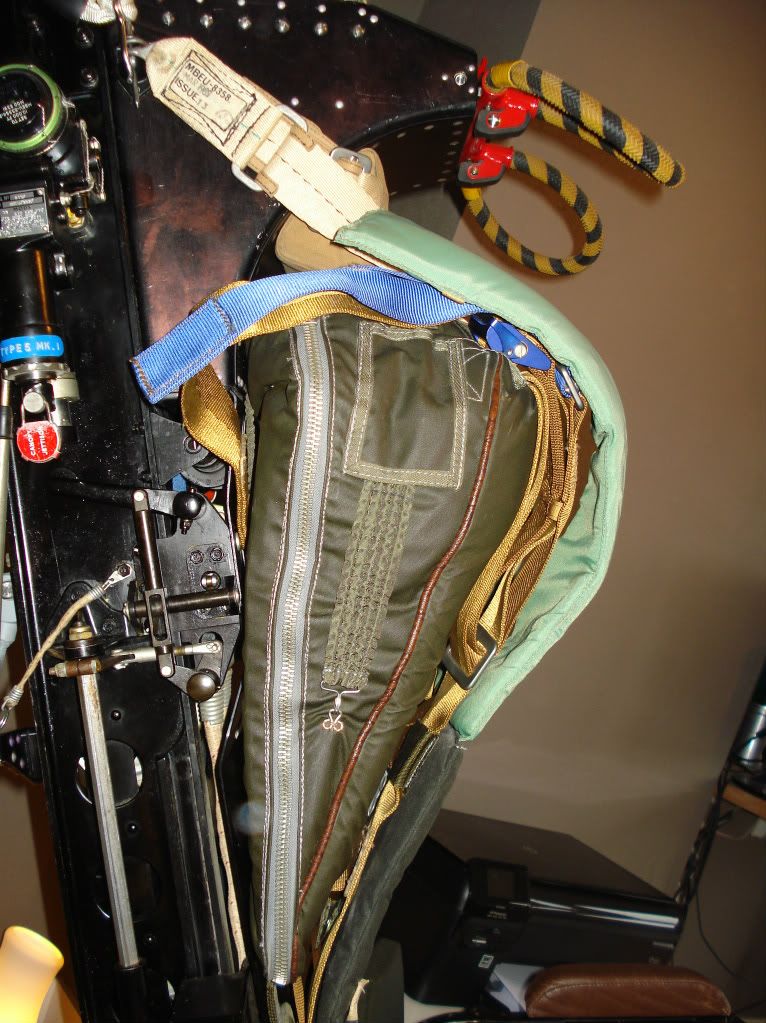
I'll start off with the left hand side of the seat (seating direction):
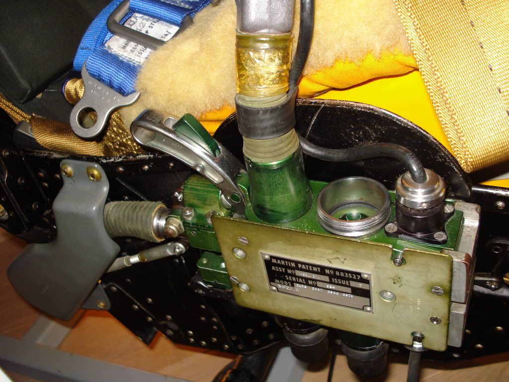
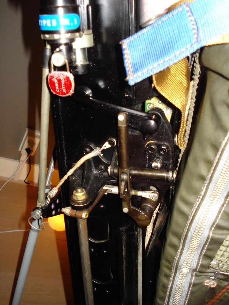
This is the release handle, as you can see it is black and gold colored.
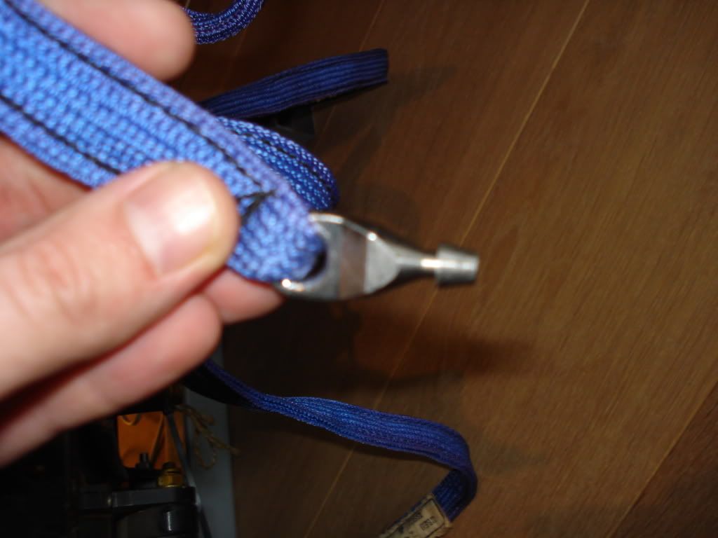
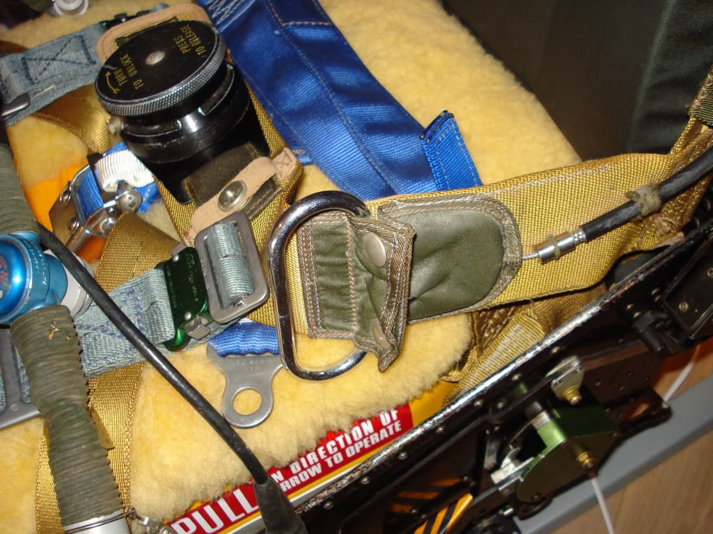
The next is the leg restraint system. It is basically a clip that goes in to the seat:

Then runs trough the cutting meganism:
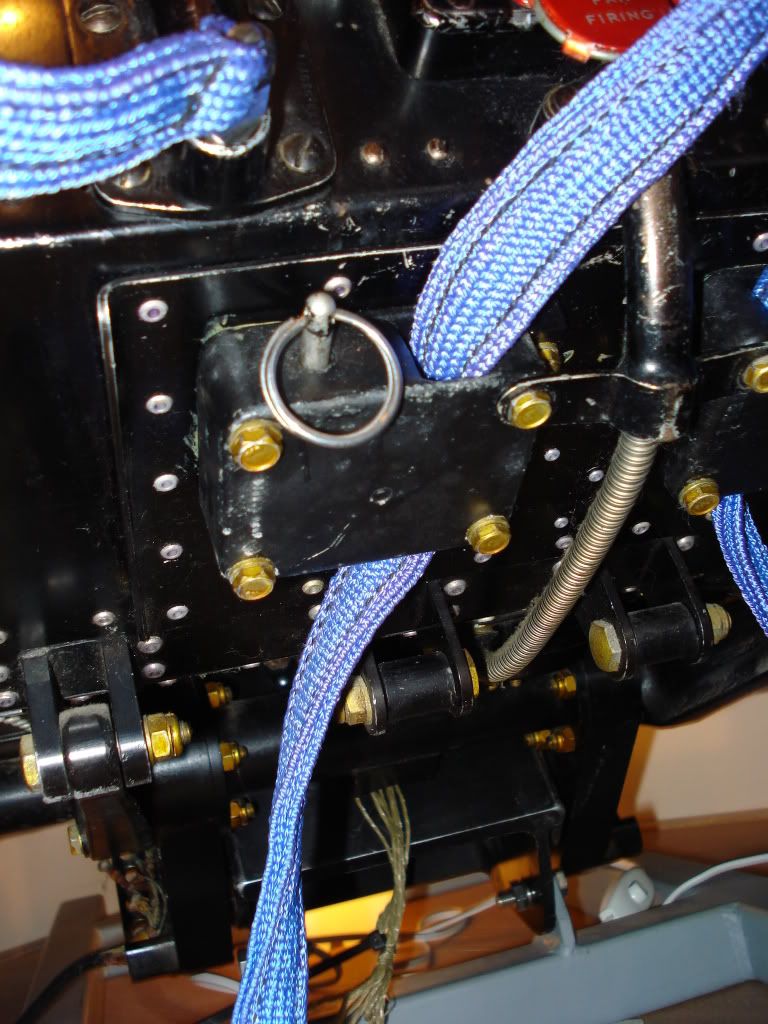
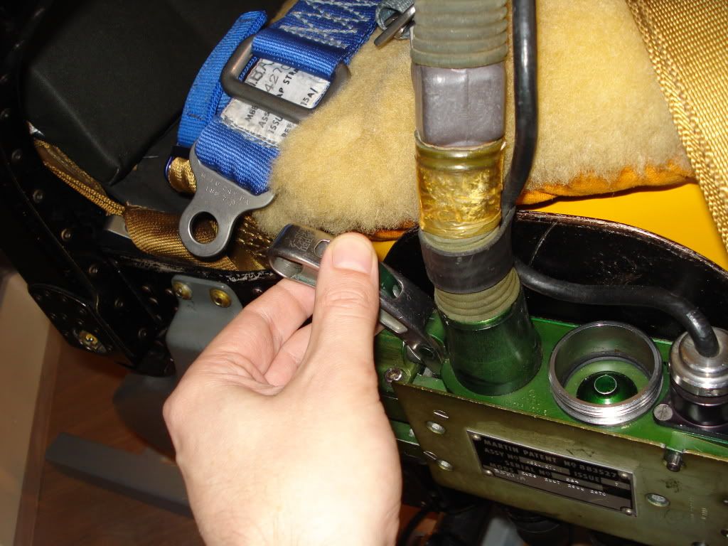
you can pull the ring on the cutting meganism to take the whole strap out ouf the seat(when the seat was removed for maintanance etc.)
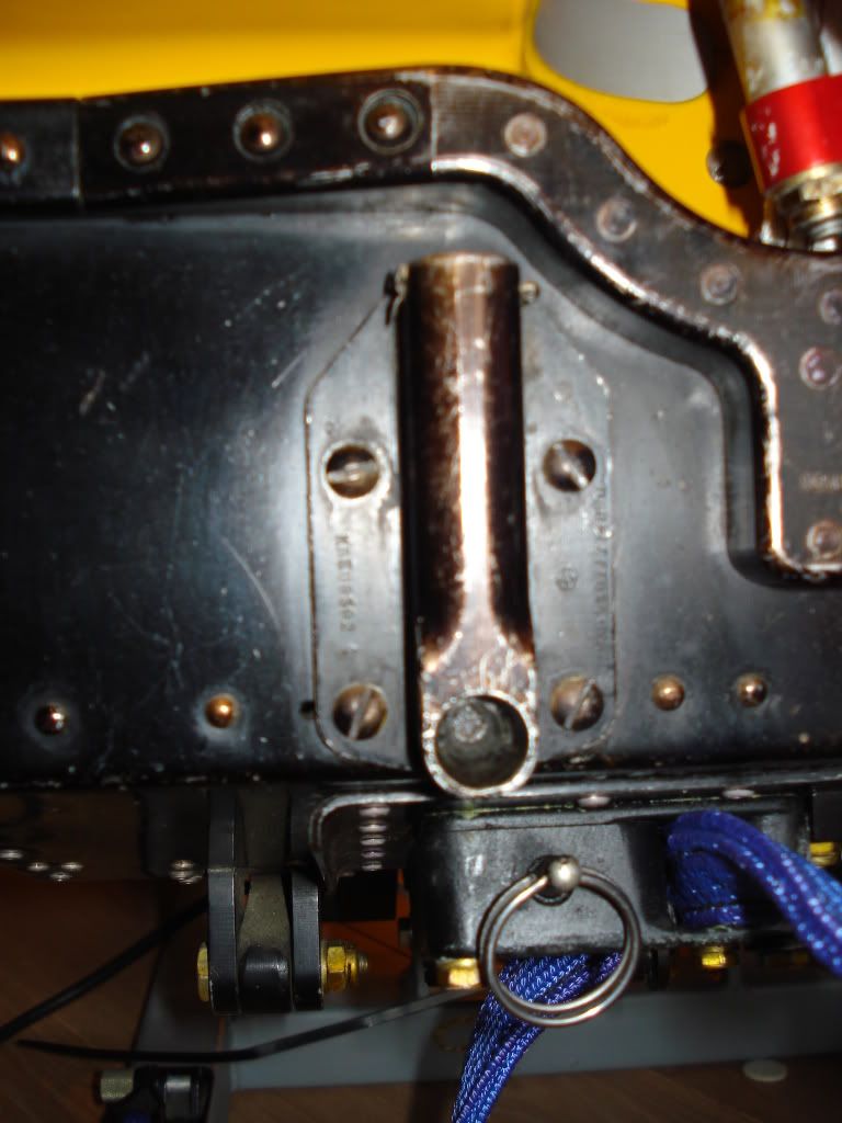
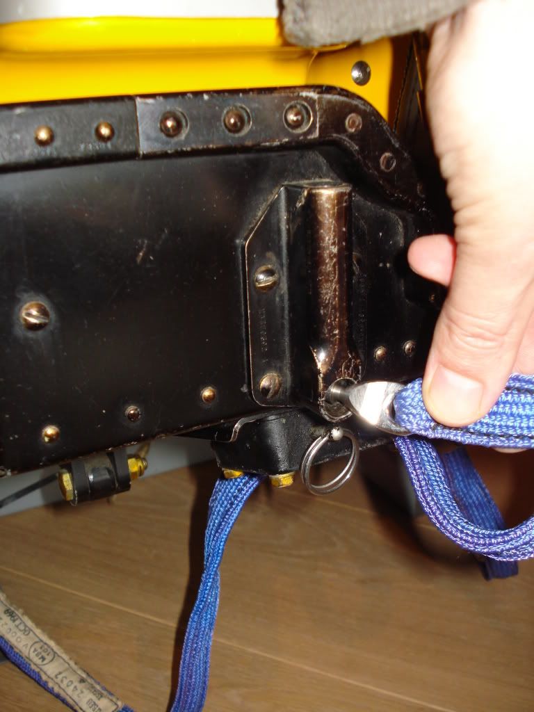
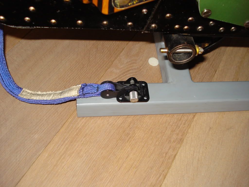
Then it goes to the bottom of the aircraft where it is connected to another clip, so if you eject from the aircraft the restraint gets pulled and finally cut by the cutting meganism:
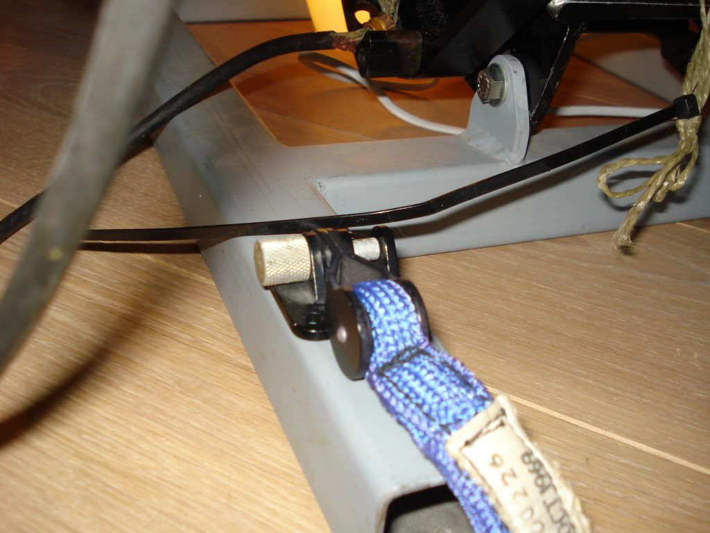
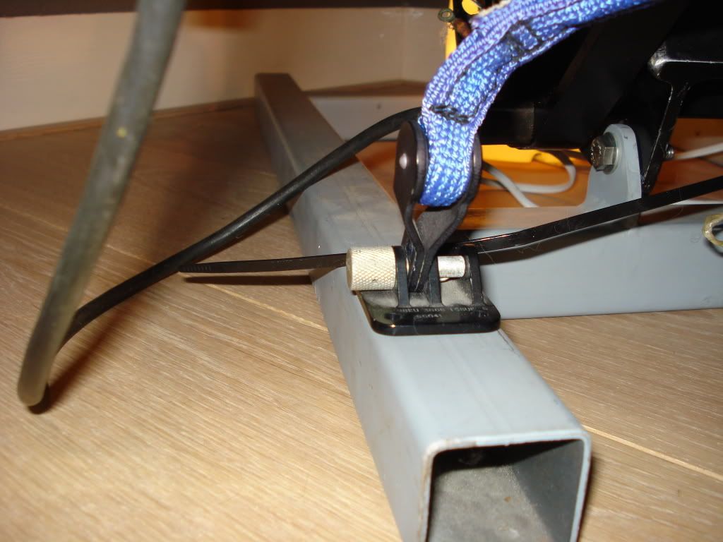
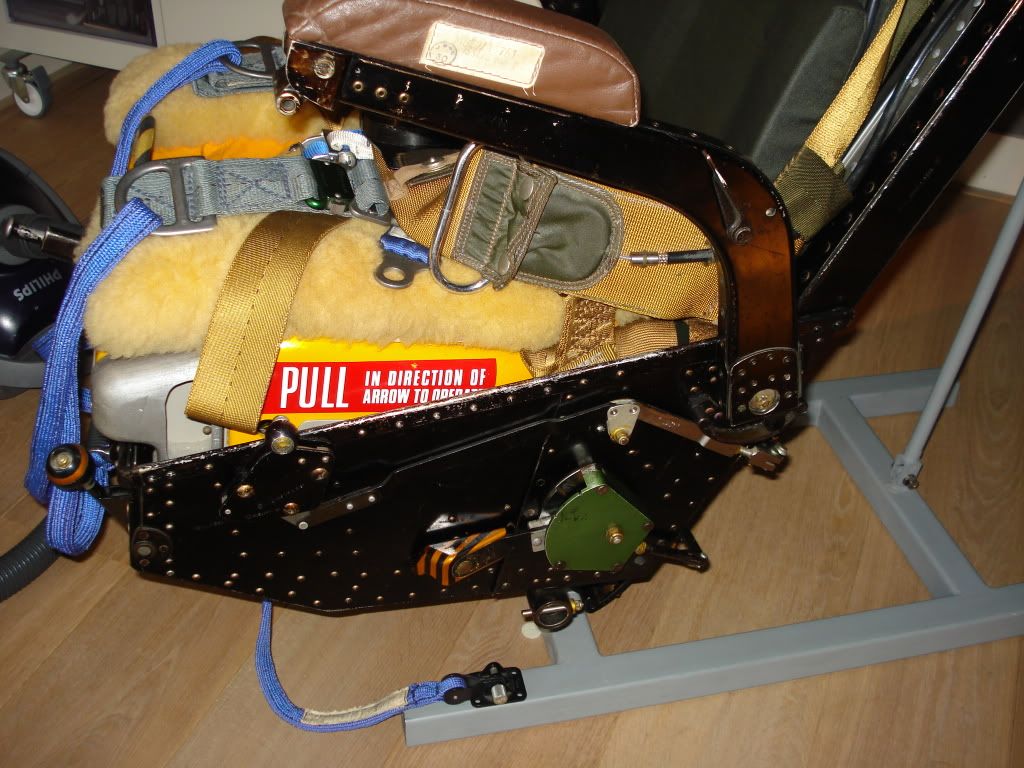
To release yourself from the leg restraint system just pull the lifesupport package handle and the clips release (fall out ) of the seat:
The link between lifesupport and leg restraint system:
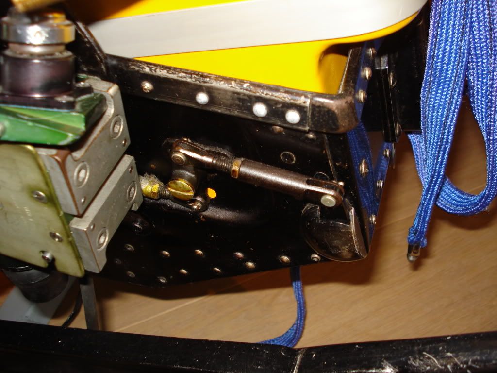
The clips:
To reconnect: do the opposite i.e connect life support and the as it is locked plug in the clips again:
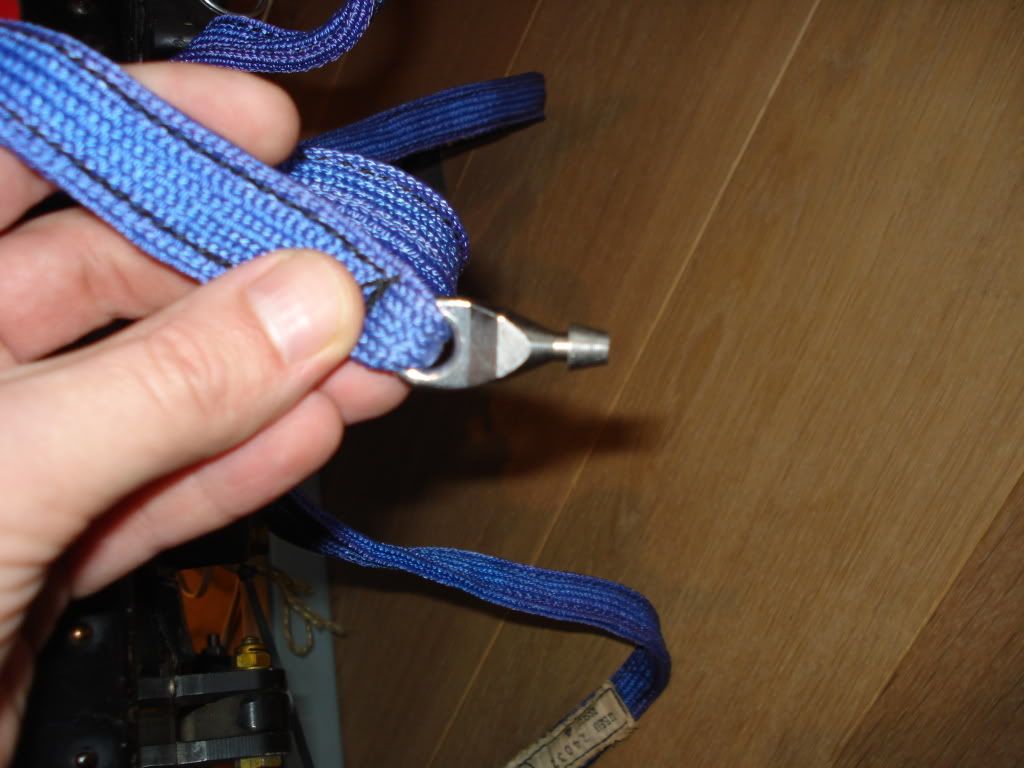
The leg restraint straps :
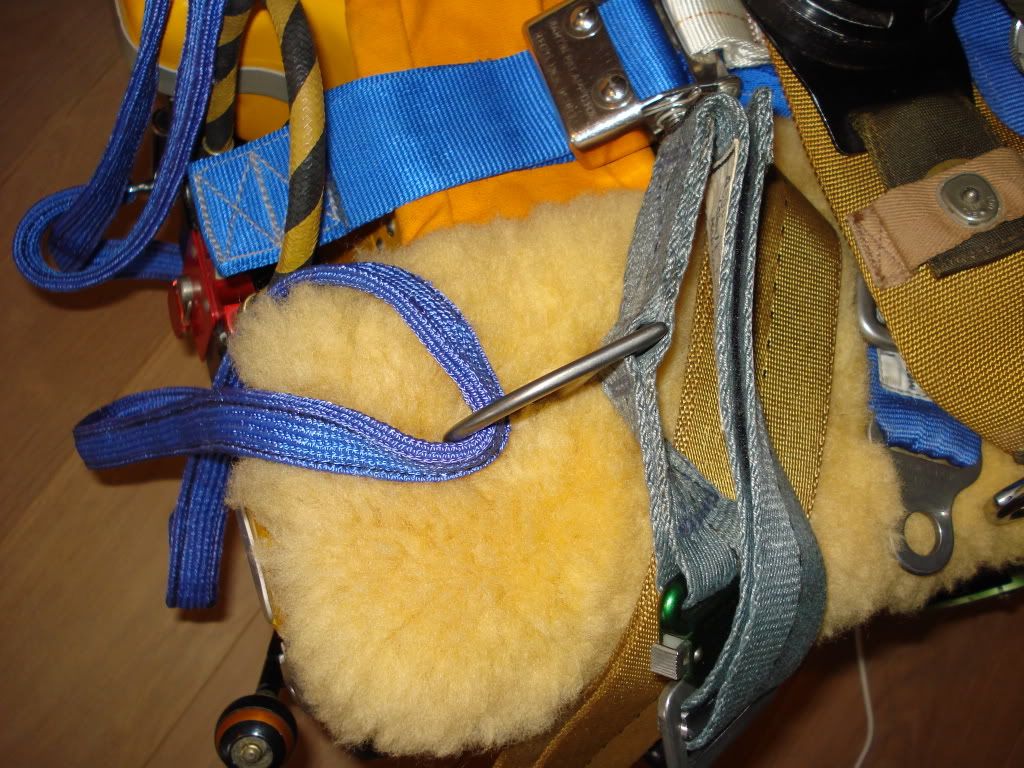
All connected:
The parachute handle:
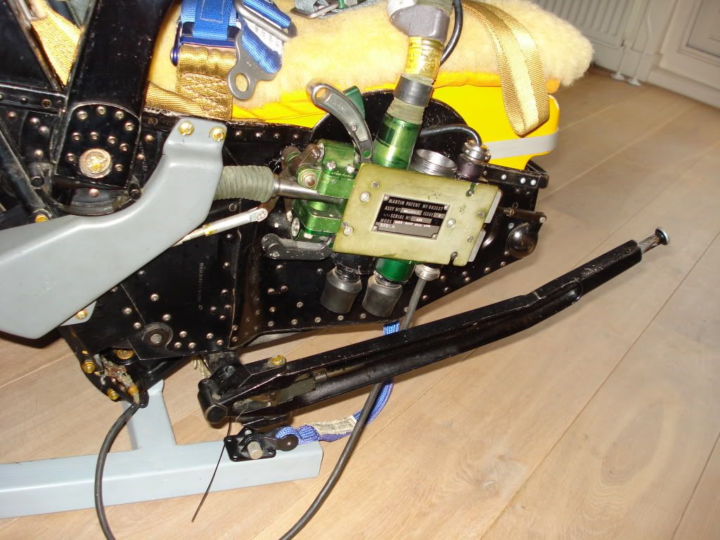
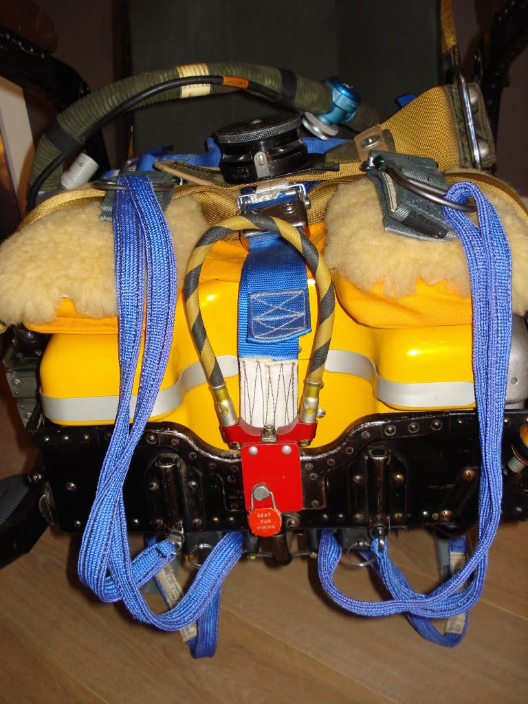
top backside of the seat: (canopy and the seat firing meganism)
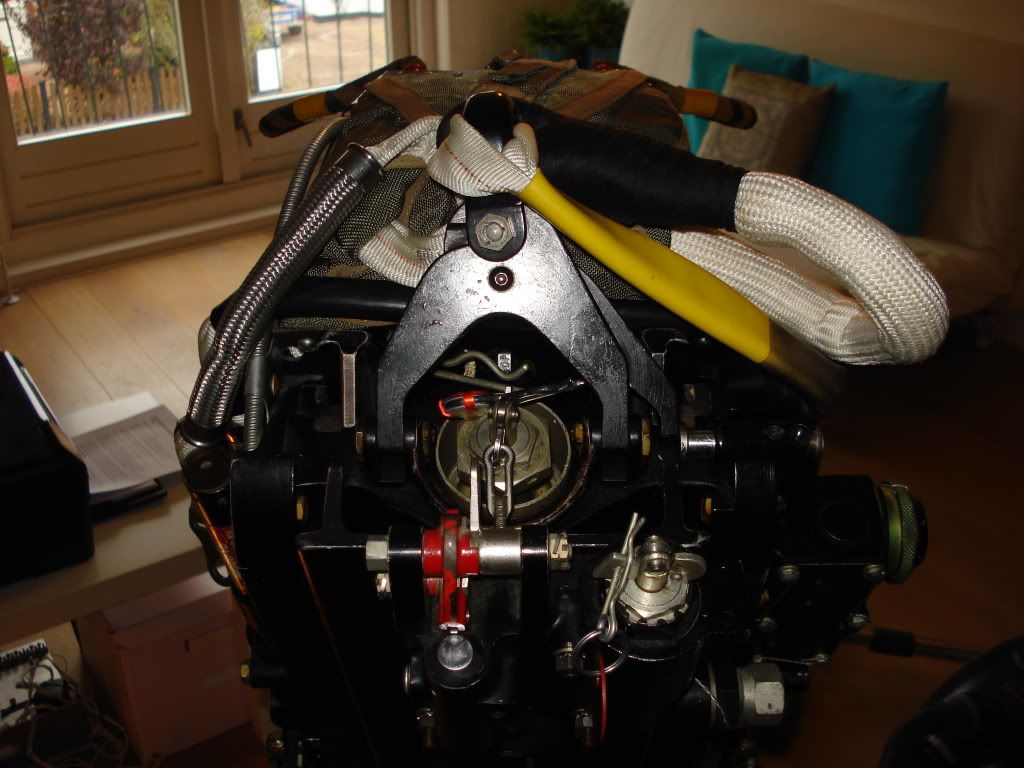
Top right: (barometer unit that activates the release meganism): Wich is atached to the seat rail ( installed in the aircraft i have my seat installed on the real rail and fixed that to a display rig)


And some general pictures:
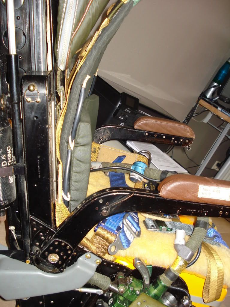
 .
.
I hope this will help you out!
Best regards ,
Remco
-
11-02-2011, 03:18 PM #1610+ Posting Member
- Join Date
- Aug 2011
- Location
- Australia
- Posts
- 16
Re: Vulcan Bomber...
Thanks REMCO for taking your time to take all them pics and putting together that post. You have exceeded my expectations, several times over. Gonna have to sit down with a coffee and study. Thankyou. Cheers.
-
11-02-2011, 05:12 PM #1775+ Posting Member
- Join Date
- Mar 2010
- Location
- Netherlands
- Posts
- 131
Re: Vulcan Bomber...
Your welcome ! I am glad I could help out !
If you need more pictures just tell me then I'll make some more.
Good luck studying
Best Regards Remco
-
11-24-2011, 03:13 PM #1810+ Posting Member
- Join Date
- Aug 2011
- Location
- Australia
- Posts
- 16
Re: Vulcan Bomber...
http://youtu.be/AzVTE_exvjg
This a vid that i made a few months ago. It feature the IRIS sim Vulcan B2 flying over the Pacific north west USA scenery by ORBX. This vid was partly responsable for inspiering my home cockpit. Please enjoy. Cheers.
Ive made some more progress on the first of my ejection seats. I just got my copy of FSPanel studio and am yet to experiment with it. Also got a pair of Saitek pro flight throttle quadrents. The throttles were easy to set up and fun to use. Lets hope there reliable. Cheers.
-
11-24-2011, 04:01 PM #1925+ Posting Member
- Join Date
- Apr 2010
- Location
- surrounded by hostile natives.....NE Anglais
- Posts
- 38
Re: Vulcan Bomber...
I've got x2 saitek throttle quadrants, they are doing ok so far (had them just over a yr) the saitek yoke is another matter though, tis a P.O.S! luckily you just need a joystick!
 FSpanel studio is a good bit of kit, used it for my lanc panel and extra pop up screens until I can get more monitors.
-
11-25-2011, 01:38 AM #2010+ Posting Member
- Join Date
- Aug 2011
- Location
- Australia
- Posts
- 16
Re: Vulcan Bomber...
Thanks for your comments. Yes the Vulcan does have joysticks, but they do not stick out of the floor like most jets. The Vulcan joystick, sticks out from the main instrument panel. So i will be using two yokes, but the normal two handed "yoke type" grips will be removed, and replaced with a single stick with the usual buttons and triggers etc This set up goes left and right, and in and out, just like a yoke on a Cessna. I will heed your warning re: Saitek yoke. Im either gonna use a pair of commercially available yokes and modify them. Or. I will build from scratch. Ive been toying with the idea of useing a mountain bike suspenion fork leg for each yoke. First, seperate left and right leg from each other. Remove the springs from the forks, and adjust dampening and fork fluid weight to adjust the feel of the in/out of my new yoke. The fork staunchion will rotate left and right within the staunchion outers for bank left and right. Fabricate and fit a joystick to each leg. Then mechanically link the left and right units together useing heavy duty, stiction free, rose jointed link. Then set up potentiometers and card to make it work. Not sure how i will run wires from joystick switches as the stauchion will be full of fork oil and sealed up. Any suggestions greatly appreciated. Cheers.

 Reply With Quote


Candid connections: Platform for casual relationships Live Women Prime Сasual Dating
Super Сasual Dating - Genuine...