

Results 11 to 20 of 37
Thread: Glenn's Generic Fighter Pit
-
05-23-2009, 12:10 PM #1125+ Posting Member


- Join Date
- May 2009
- Location
- Sydney, Australia
- Posts
- 47
Reconstructed Log
Posted: Sun May 16, 2004 1:44 am
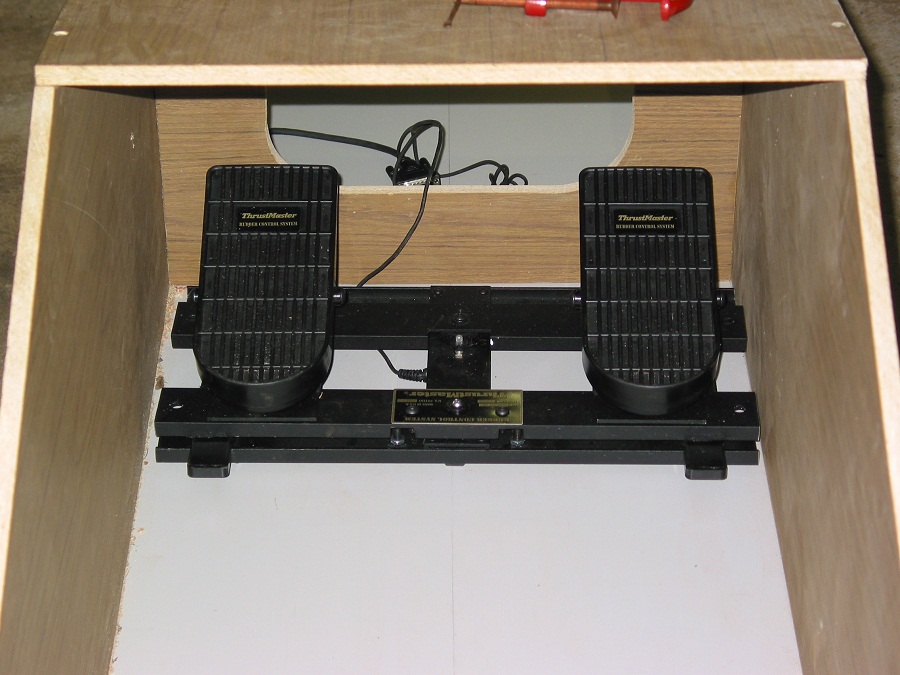
G'day once again, Have now received my rudder pedals that I purchased off ebay, these pedals are a very old thrustmaster RCS model, however they are very easy to modify, This set has been reduced by about 4cm in width to fit into my pit, the job was fairly easy to do, it took me a nights work to complete, They don't have toe brakes but I am planning on another mod to add them, I actually found some plans on the net in regards to the toebrake mod, but that will be done later.
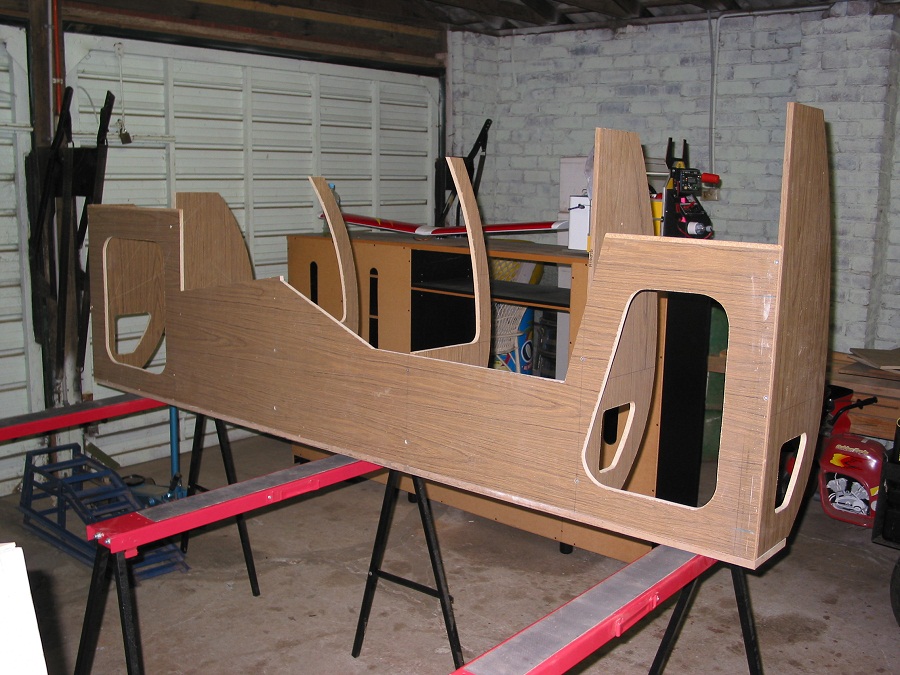
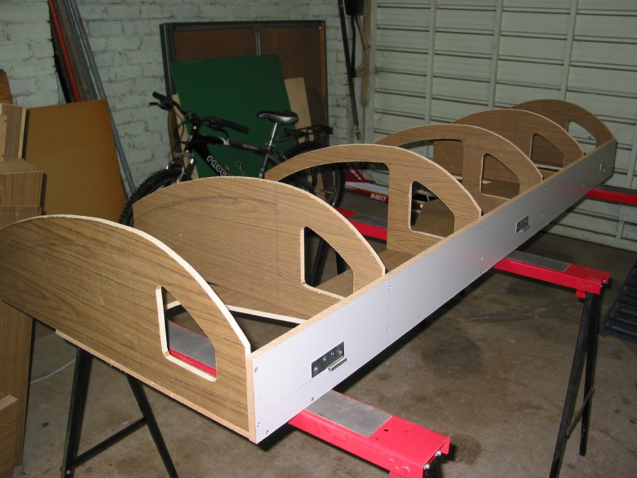
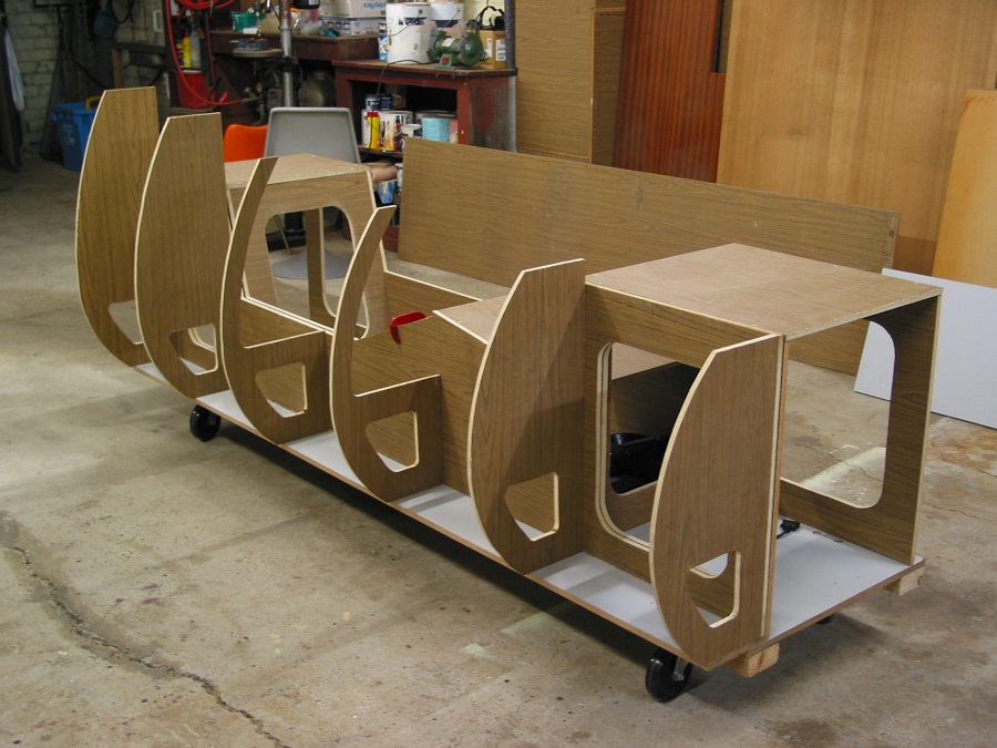
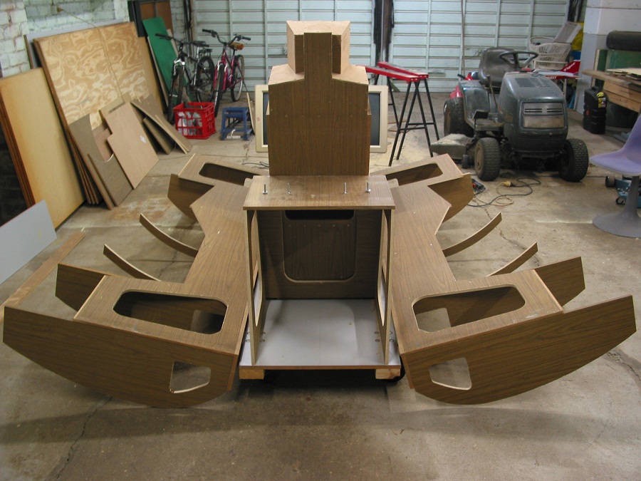
Meanwhile work on the main structure continues........... I have now got the Right hand side basically assembled & hinged along the floor line.
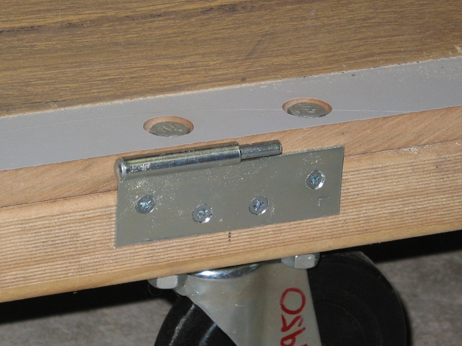
The hinges are a dismountable type & can be picked up for only a few dollars at any hardware store, this allows for easy disassembly of the complete structure & will allow easy access when wiring or carrying out maintenance to the pit, On that note I also have decided not to use glue in any parts of the assembly thus the whole pit will be able to be dismantled all the way down to flat boards should the need ever arise.
I have taken a shot to show where main cabling will run down the side of the pit, I decided to cut the same holes in the end of the sides as well to allow data & power cable feeds into the pit, this should keep the main PC housings at the front & back free for hardware such as PC's, hubs etc.
I have now ordered & waiting delivery of a thrustmaster hotas system, unfortunately not the hotas cougar but the model before it, once the system is up & running I will consider the more expensive cougar unit.
Anyhow here are some more piccy's to see.
Glenn.
-
05-23-2009, 12:13 PM #1225+ Posting Member
- Join Date
- May 2009
- Location
- Sydney, Australia
- Posts
- 47
Reconstructed Log
Posted: Sun May 16, 2004 1:54 am
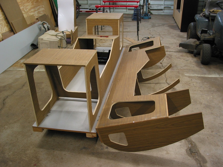
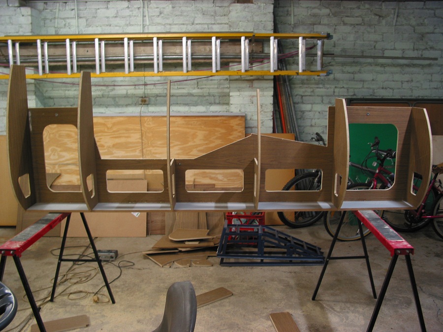
Here's pictures of the assembled side fitted & hinged, you can now see where the side control panles will be housed, I still have to cut out some more access holes in just underneath where the side panels are to lay.
The whole side can easily be handled by a single person, it is put on by simply placing it onto the floor overhang with it offset a few cm to the front of the main pit, then pushed onto the hinge pins from the front of the pit, a couple of good taps & she's locked in.
-
05-23-2009, 12:48 PM #132000+ Poster - Never Leaves the Sim

- Join Date
- Oct 2006
- Location
- Southern Illinois, USA
- Posts
- 2,887
Yes, it can be hard to find those odd parts. These are good folks to deal with and keep checking back at the site, always something new to look at.
I bought a very nice utility Duzs railed rack for the captain's side panel in the B727. You never know what you'll turn up there.Boeing Skunk Works
Remember...140, 250, and REALLY FAST!
We don't need no stinkin' ETOPS!
Powered by FS9 & BOEING
-
05-24-2009, 12:06 AM #1425+ Posting Member
- Join Date
- May 2009
- Location
- Sydney, Australia
- Posts
- 47
Reconstructed Log
Posted: Sun May 16, 2004 1:57 am
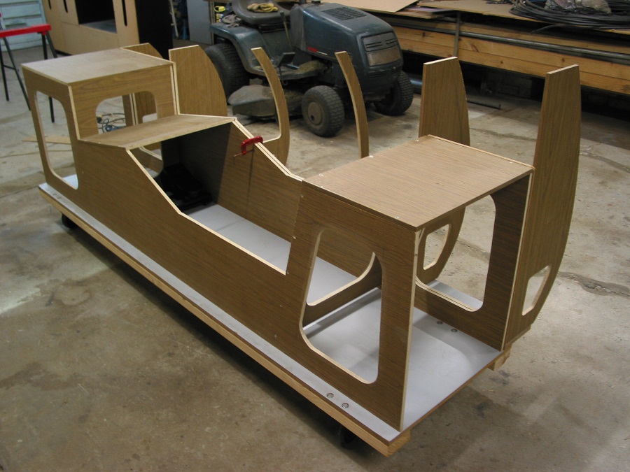
In position & held by a clamp at this stage.
I now have to disassemble this side & I am going to use the existing ribs as templates to cut out the left side, lucky I didn't use glue !!
-
05-24-2009, 12:09 AM #1525+ Posting Member
- Join Date
- May 2009
- Location
- Sydney, Australia
- Posts
- 47
Reconstructed Log
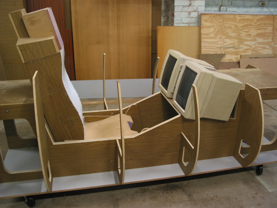
Posted: Sun May 30, 2004 1:19 am
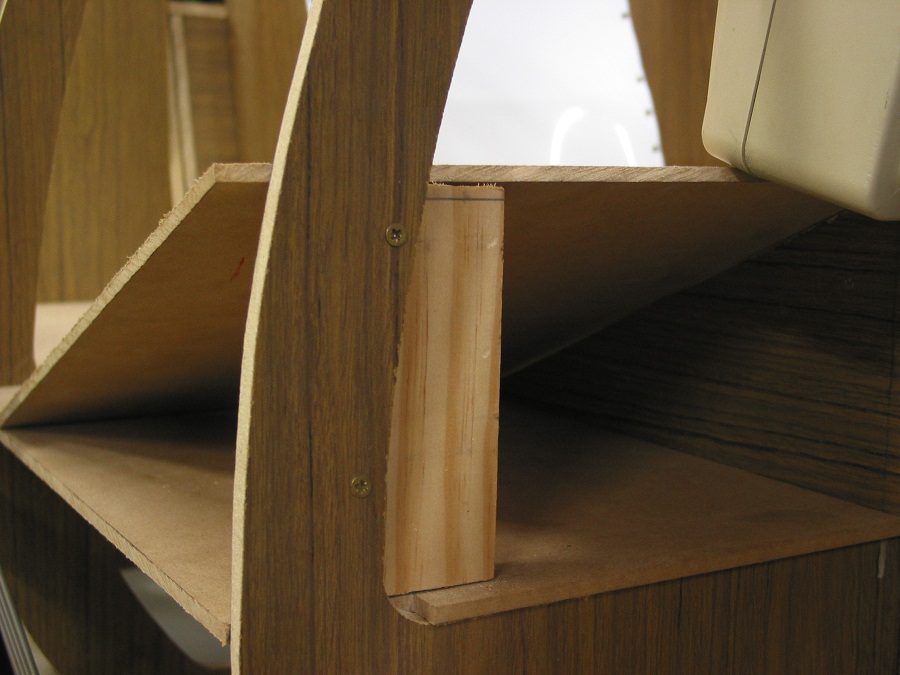
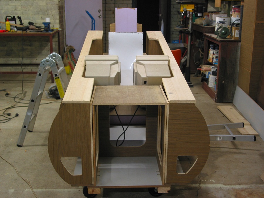
Hello Once again, Have now constructed the bulk of the left hand side, it is now hinged & I have installed fasteners to hold the sides in place, so I don't have to keep using clamps.
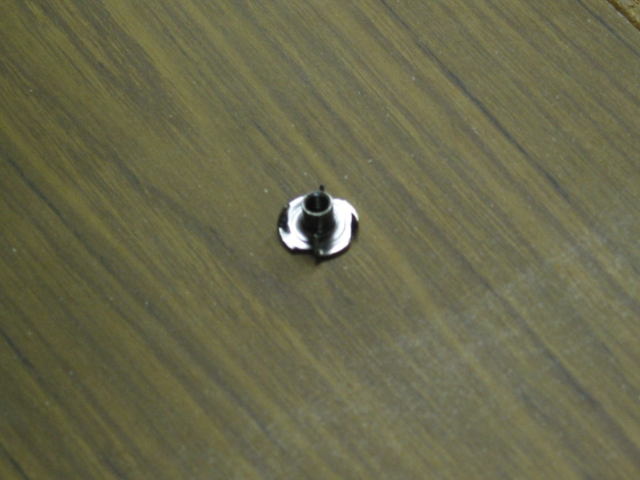
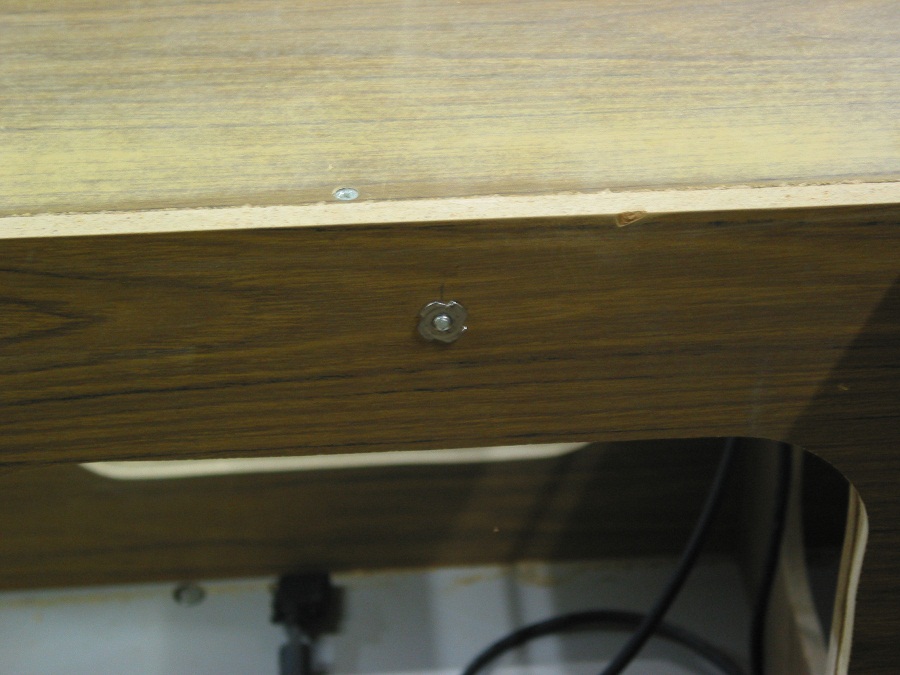
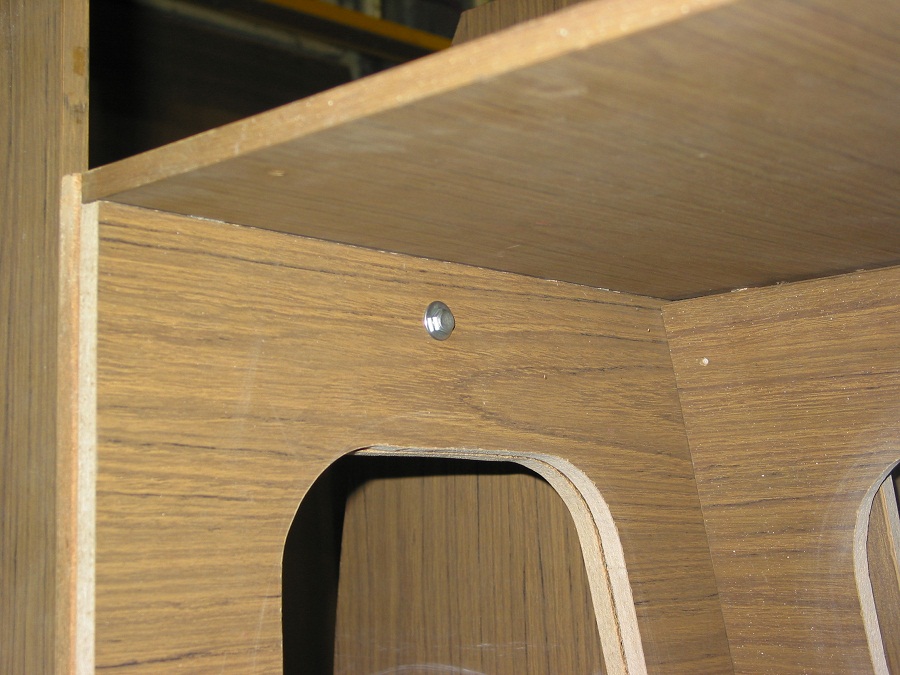
I used what they refer to in the hardware shop as a "T" nut, often used in the end of table legs to allow the legs to be screwed onto a table, I think they maybe also referred to as a blind nut, I recall seeing them called that in a hobby shop, but I could be wrong. The ones I have used are 1/4" Whitworth thread & do the job just nicely.
I used a countersink head bolt near the seat so it would not interfere with the seat adjustment back & forth. I used a standard Hex bolt in the other two area's where I have fastened. 3 bolts in total on each side, Front, middle & rear.
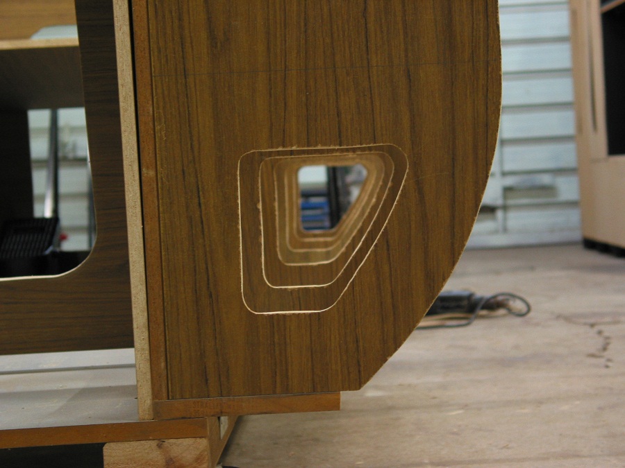
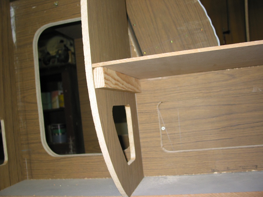
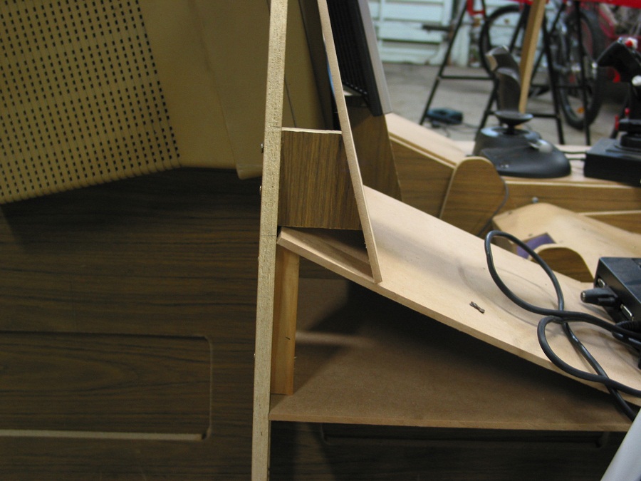
I have also now cut out the extra access port holes in the sides to allow me to get my hands in underneath the panels once they are mounted.
I have purchased the top rail for the sides, this is going to be tricky to mount onto the ribs with the angles involved but not impossible, I want to cut a slot into the rail where each rib attaches to create a better join.
I have also purchased some 6mm MDF for the blank panel base & am now planning on on how it is all going to be mounted, again with the curvature of the outer skin when fitted this will get interesting, I may use some cardboard to get the rough shape before I commit to saw cuts.
Thats about it for now, hopefully the next update after this one, I will have a blank MDF panel & I can start to plan where things are going to be placed.
Cheers Glenn.
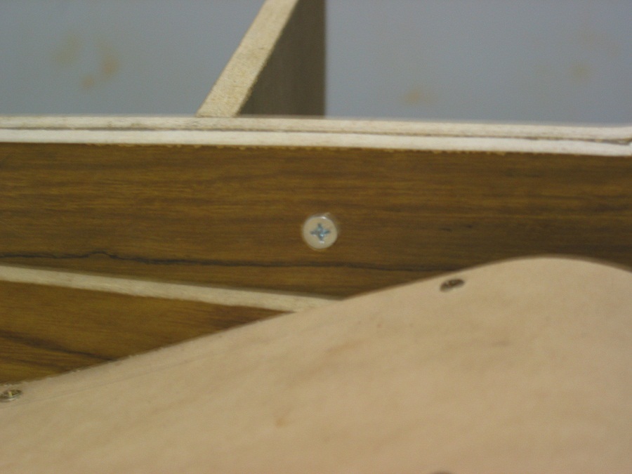
Hex bolt & Access ports
-
05-24-2009, 12:15 AM #1625+ Posting Member
- Join Date
- May 2009
- Location
- Sydney, Australia
- Posts
- 47
Reconstructed Log
Posted: Sun May 30, 2004 1:25 am
All fastened together, these shots were taken before the access ports were cut out.
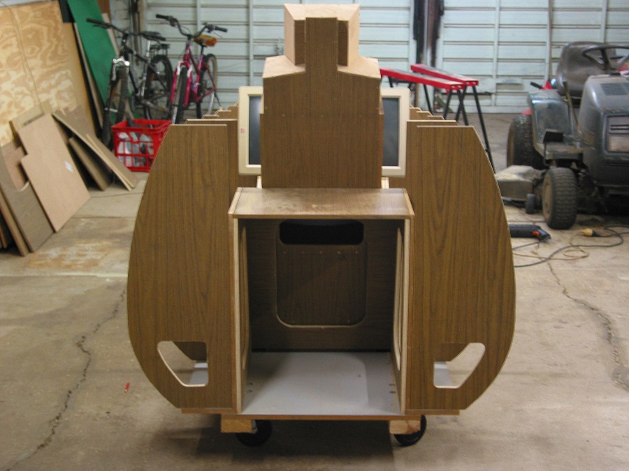
This is a shot taken from the rear overlooking the top of the seat, you can see here the width & basic shape of the front panel.
-
05-24-2009, 12:20 AM #1725+ Posting Member
- Join Date
- May 2009
- Location
- Sydney, Australia
- Posts
- 47
Reconstructed Log
Posted: Sat Jun 19, 2004 2:46 am
HI..........Back again for another update.
Well I have now cut & fitted the top rail for the sides, I took the rails down to my brothers place as he has a routing table & routed off the top corners for me, I am happy with the results, no sharp corners to knock up against.
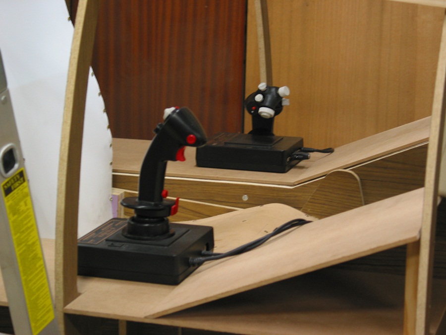
Well my HOTAS system arrived from ebay, I tested it all out with rudder pedals connected & everything looks serviceable. I have taken some piccy's of the controllers but that is not exaclty where they will be located, I am going for the stick between the legs format, although I have not completely ruled out a side stick mount either.
Finallly I cut the side console panels, heaps of room for switches & stuff so I can't wait to get stuck into the panel fitout, I just need to get the front console done & I think I may then start the paint work, I have now ordered 2 sheets of the bending ply that I will be covering the exterior with & hopefully they will be here next week.
Over the top of the monitors I am planning a glare sheild, not sure exactly how it will be constructed yet but I am starting to come up with a few ideas, now the side rails are in place.
It will be removable so I can access things, I am also considering a canopy but that is not high on the priority list as it has no bearing on getting the sim up & running.
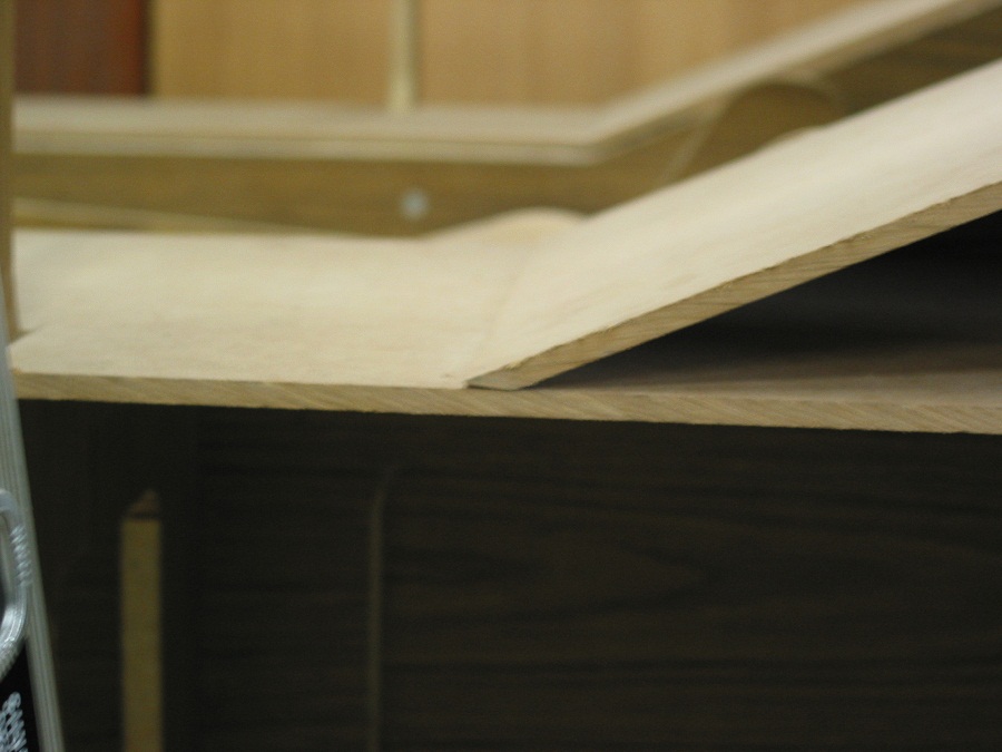
For the panels I have used 6mm MDF & I must say it's great to work with, however it is reasonably soft too, so you have to be carefull not to drop the board or the corners will be easily squashed & go out of shape......Keep it out of reach of water too, it's like a sponge.
I found the 6mm stuff is quite strong & self supporting, as you can see my panels will not be affixed to a base all the way around but they are still very sturdy with this arrangement.
Well I now have to climb a ladder to get in & out of the pit, thats just what I wanted. I beleive it's the first step to true immersion into the sim, you need to feel like you are getting into something & climbing into this thing does just that. I will probably build a specially designed ladder or see if I can use a short set of steps from down the harware store but the the folding ladder here will do the trick for now.
Anyhow enough rambling, here's the latest pictures.
Cheers Glenn.
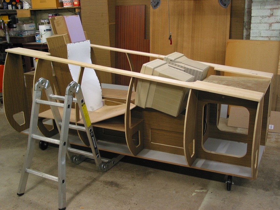
OH yes by the way I chickened out on the chiselling of the top rail where the ribs join onto it, it was just too difficult with the angles involved.
Some more.........
-
05-24-2009, 12:27 AM #1825+ Posting Member
- Join Date
- May 2009
- Location
- Sydney, Australia
- Posts
- 47
Reconstructed Log
Posted: Sun Aug 15, 2004 12:59 pm
Hi once again, well things have slowed down a little, mainly due to the fact that it's the middle of winter & just a bit too cold for me down in the shed, other factors that have held me up a little are:
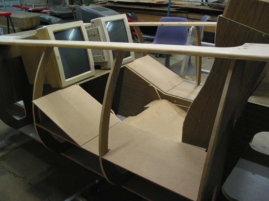
I have been trying to work out in my head just how I was going to handle the centre console & front instrument panel, I have litterally spent weeks going over it in my head & allthough it looks pretty simple it isn't when you have nothing there & no plans to work off, the toughest bit was getting the angles correct, however I think I have come through with the goods & things seem to have worked out.
I also found that the seat was way too close to the dash & have now made an adjustment to the main tub so the seat can be further away.
I have now decided on a side stick mount similar to what you find in an F-16, simply due to the fact that because I want to do a duel seater & hopefully mechanically link the control sticks, the actual gymbal mechanism would have to be on the floor, therefore I would have had to extend the stick, this would then cause the controller to hit the front instrument panel in the full forward position..........not good!
So I am now opting for the side stick position, this should also make mechanical linking to the rear seater a little easier with the control rod running down the side of the pit. I HOPE !!
Having a side stick mount also makes seat forward/aft adjustment simple and infact I can have the seat right up to the console........I have two little blokes 5 & 9 yrs old, I am sure they are going to want to fly this thing so I had to take this into account.
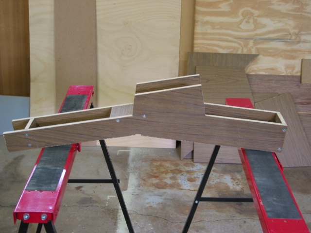
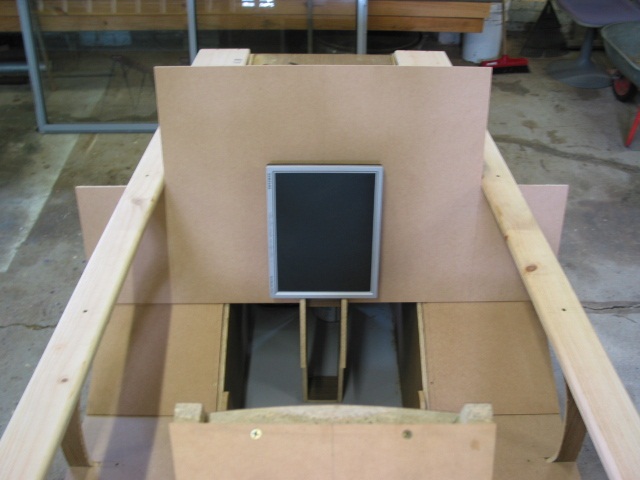
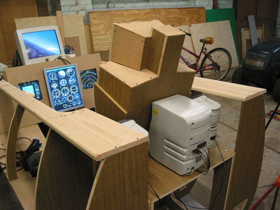
So there were a few decisions to be made at this point of the build & thats what has slowed me down, thinking ahead is paramount & can save much work later down the track, so I am happy with it so far, as you can see I now have some trimming to do around the panels to get them into their final shape, the front instrument panel will not be that high it will be cut down to a sensible height.
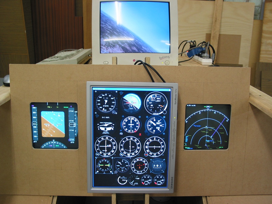
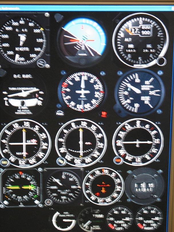
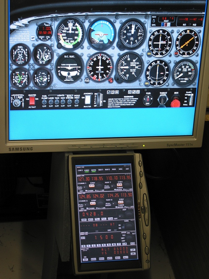
So as you can see, the front panel goes like this, left CRT cutout in the new panel for the PFD, centre mounted LCD for primary instruments & will be a full IFR layout they will also double as STBY insruments for GC, right CRT cutout for the ND, I will probaly have some video switching for EICAS display & maybe other things like GPS, just have not worked out the logistics of it yet, I am planning a 7" Widescreen TOUCH VGA monitor on the RH console mounted vertically for an FMC, this may also be setup to switch to GPS screens & SB screen when typing maybe required for VATSIM, as I said stilll many things to work out but I will not fully know which way to go until I can sit in front of all the screens with them running to really know where I want things to be.
Cheers Glenn.
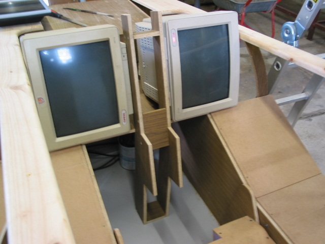
Front instrument panel fitted but not screwed down just yet.
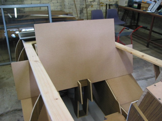
LCD display will be hosting the custom instrument layout I created within flightsim, the panel will be undocked & moved to this monitor using an extended desktop.
-
05-24-2009, 12:35 AM #1925+ Posting Member
- Join Date
- May 2009
- Location
- Sydney, Australia
- Posts
- 47
Reconstructed Log
Posted: Tue Oct 26, 2004 2:06 am
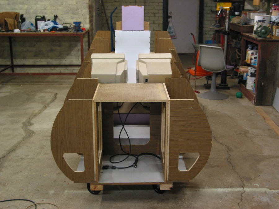
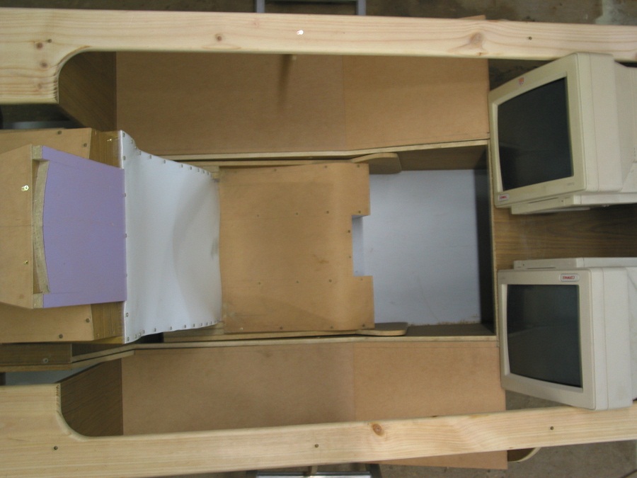
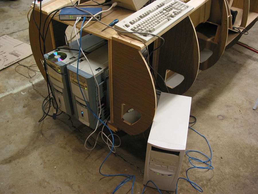
Well it was time to see some action I thought, so I hauled all the computer gear down to the simulator & thought I would see if I can get it all together, at least the displays anyhow & perhaps sit in it & go for a quick joyflight........................
Well it certainly wasn't quick to setup, lots of cables & plugs & this is just the tip of the iceburg, won't it be nice when you can build a whole cockpit using bluetooth components !! I wish !
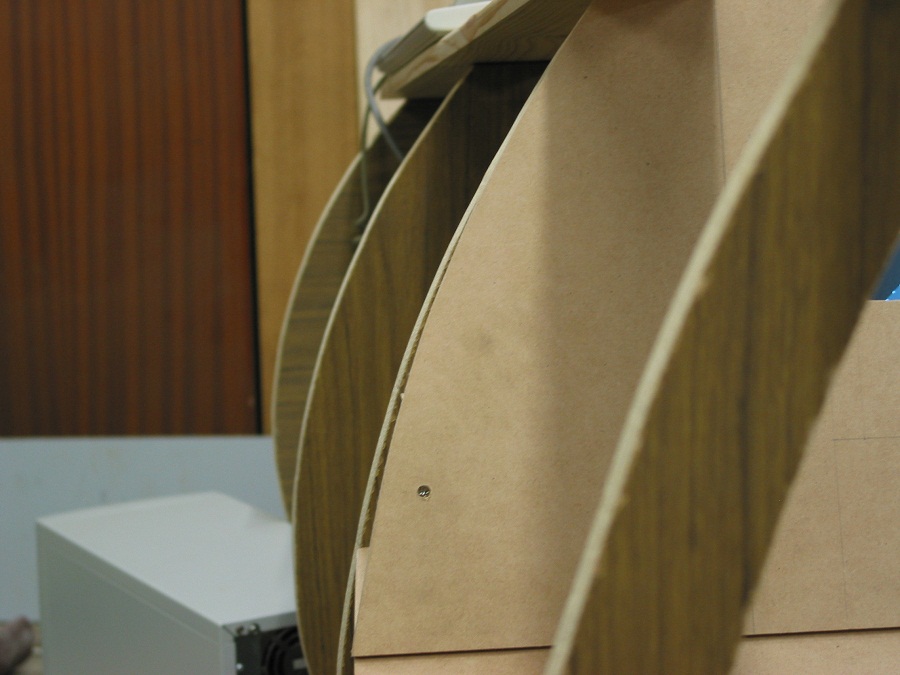
Anyhow I finally settled on the position/size for PFD & ND display cutouts, The Front panel is now srewed down & I have now shaped the sides of the front panel to the body of the sim as shown in the pictures below, the angled side panels have also been done but are not as noticeable as it was a very shallow curve, I used a clever little tool that I have had since my Tech drawing days from school, it's called a French Curve & can be purchased at any drawing supply shop. It's just a flexible type of ruler that can be bent to odd shapes to allow you to draw unusual curves, I just eyeballed along the hull & kept bending the french curve till I thought it looked pretty good, once it looked OK I then drew a line on the panel & Jigsawed away, I have checked the curvature by putting a peice of the hull skin along the ribs & I could not have got it any better any other way.
So now the fun begins, getting all the avionics to work, well the displays are a minefield in themselves, don't expect anything to work the way you think it should unless you have tried it & seen it for yourself.
I am sorry if this next bit is a little boring but this area is a major problem in simpit building........Skip it if you like but there are lessons to be learn't here.
Multiple Displays ?.........The big question, hows it done, what to do, what to buy & what are the limitations.
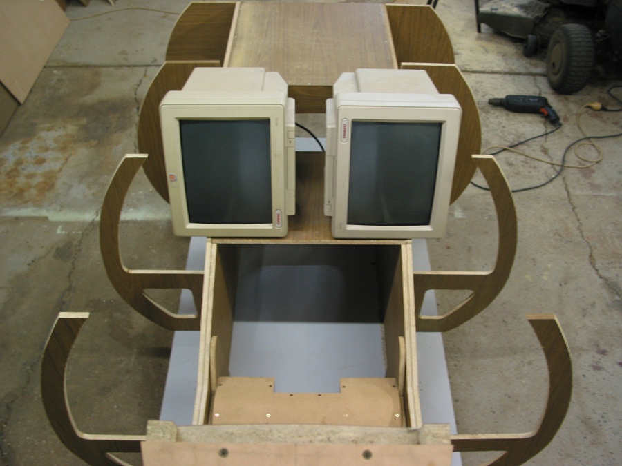
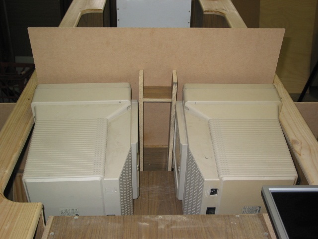
OK I will Take this from my perspective, there are lots of different ways to impliment your displays in a pit but those CRT's were given to me for free & I could not pass that up, so I made use of them in the pit, I was given 5 of them in fact. They will probably be replaced with LCD's eventually.
This was my theory, Buy a good dual head Display card for the Sim, The primary display Will be the Front (Out the Window View) & will eventually be displayed by projector, the second display will be the undocked custom FS instrument panel that you see on the LCD, My specific problem here is that the Instrument panel monitor needs to be rotated 90Deg cause it's on it's side, Well the latest Nvidia drivers have a thing called NVrotate so you can rotate your display however this cannot be done on a dual head card with desktop spanning switched on, I was caught out on this one, If I did not have the requirement for rotation then I would have been OK I think.
So I ended up buying a Geforce FX5700 Dual head & found all this out the hard way, By the way previous to that I bought a FX5200 dual head card & found out it just would not support desktop spanning at all, only display mirroring, which I had no use for at this point.
So Once I found I could not use the desktop spanning on the 5700 dual head I then went & purchased a PCI Geforce IV MX400 card to run as a second display card for the instruments, by the way for NVrotate to work the minimum display resolution has to be 1024x768 & the card has to have a GPU on board, so it has to be a Geforce IV or better, the TNT II card will not rotate using the Nvidia drivers, you need to use third party software called Pivot Pro, that works OK too.
Now I know what your thinking, you don't need a 3D accelerated card for the display of an instrument panel on an extended desktop, yep you are quite right, but when you start playing with FS2004 & all the displays to be utilised in the sim are required to meet DirectX 9.0 compliance, don't bother farting around with anything less than the Geforce series cards, TNT II's might cut it but I didn't bother going there.
OK now that I had the outside view & my primary instument panel going I found out something else, when you do undock your instrument panel & move it to a second screen you will get some stuttering on the main outside view, particularly noticable in tight turns, I have found by restricting the frame rate back to 30fps it helps but is still there, I believe there is no cure for this problem & you have to live with it.
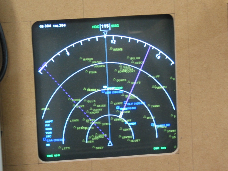
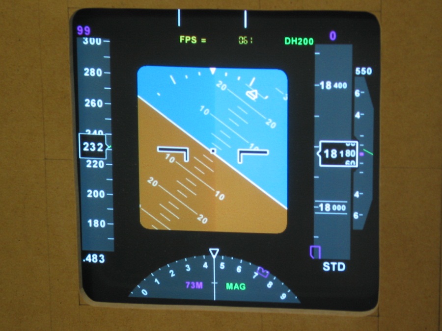
OK so on I went to the Glass cockpit arena, The pictures you see below are FreeFD Glass Cockpit displays, the right hand Nav Display (ND) & the left Hand Primary Flight Display (PFD) are running off dedicated PC's that are networked by TCPIP using WideFS & pulling data out of flightsim using FSUIPC, Search google if you are after these great little tools, all pit builders use these tools or something similar cause most sims will have more than one PC in it.
I thought I was going to be clever & run two Geforce IV PCI cards in 1 machine with an extended desktop, one display for PFD & one for the ND, nope there is no way, due to the fact that these displays are written in OpenGL graphics language & require openGL acceleration to run, Windows does not accelerate the second screen on a second card in an extended desktop enviroment, I am led to beleive it will work on a dual head card with desktop spanning as the two display are running of the primary card & are both accelerated as it is treated as one monitor so to speak, but I wasn't going out to buy another 5700, as I have spare bits & pieces laying around here it was cheaper to build another PC, So the left & right displays each have their own dedicated PC, The display cards are Geforce IV MX400 PCI's & the machines are only PIII's Running XP, one of them only has 128Mb ram, so you don't need anything too powerful. I am using the Nvidia NVrotate utility on these monitors too so the whole desktops have been rotated not just the instrument itself.
So I was caught out on a few little things & I wasn't even expecting any trouble in this area but you live & learn, if anyone has any questions about these display issues feel free to drop me a line, I have learnt quite a few things about all this in the past few weeks.
Anyway I finally got it all running & stuck the speakers up against the seat & took it for a burn......................YEP it's worth it, I have now had a taste,
Even on the little 15" monitor it was quite alot of fun, but the sound & vibration from the SUB is what makes it, I still have another SUB to mount under the seat.
I can't wait to get all the switches online now & once a projector goes in, I think I'll be living in the garage !!
Cheers Glenn.
A wireless keyboard & mouse with USB connection is handy when setting up as you can hot swap between machines & not inhibited by cables
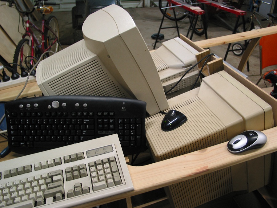
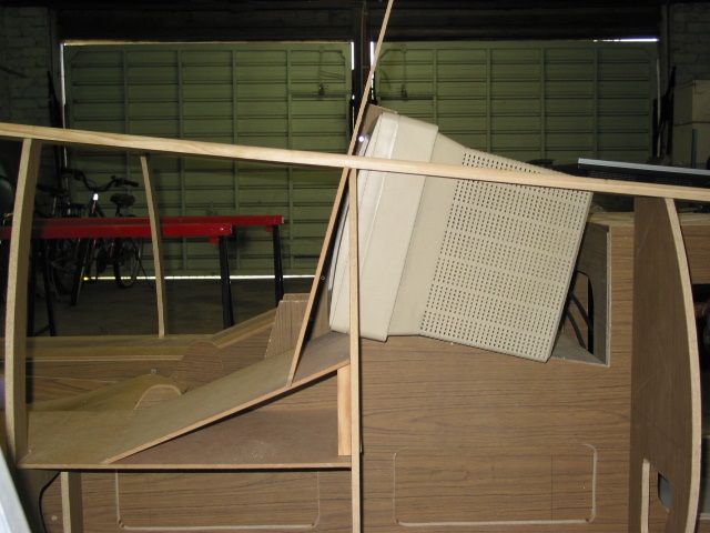
Some shots of the panel finally coming to life, by the way these CRT's give off some heat ventilation is going to be a big requirement.
Flying around in circles & out of the cockpit for the photo shoot.
-
05-24-2009, 12:38 AM #2025+ Posting Member
- Join Date
- May 2009
- Location
- Sydney, Australia
- Posts
- 47
Reconstructed Log
Posted: Thu Nov 25, 2004 12:31 am
G'day once again,
I need to correct myself on a point above in regards to to the dual head video card information I provided, I overlooked a setting in Nview's control panels for the multi monitor setup, I was trying to use spanning but this was not what I needed, I needed to set the monitors up in dual view, this way the two monitors connected to the dual head card are treated as completely seperate displays & can be independantly rotated & independant resolutions, both displays are fully accelerated too.
Sorry for the misleading information.
So Now I am running only 2 PC's, FS PC which does the out the window view & the FS instrument panel on the rotated 15" LCD, the FX5700 is in that machine.
PC no. 2 is running the Glass displays, this card is a GF4-MX400 dual head running the left & right CRT's, both rotated in opposite directions & both fully accelerated to run the PFD & ND displays.
So there you have it, this was my aim & it took a bit of time & farting around with video cards before I got it the way I wanted but it can be done.
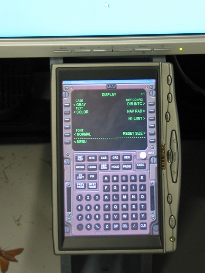
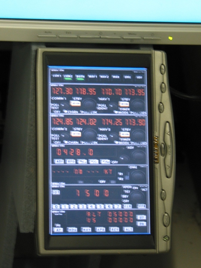
So I have now got hold of a Lilliput 7" High res Touch screen which I plan to use as an FMC in the pit, I am currently driving that display with a second video card in the PC No. 1 (The FS PC) So the FS PC has 3 displays attached to it.
I am most impressed with the lilliput display, very easy to read, touch screen works like a charm, but they aren't cheap, I landed it here from Hong Kong through ebay for $379 Ozzy Dollars including shipping/Insurance.
As you can see I had it running the standard FS radio stack, it was fully operational just using your finger for touching the screen, you do get a stylus with the unit but it is not really required to operate the radio stack.
I have also tested it with the Project Magenta's Boeing FMC, it works flawlessly.
I am building a hardware radio stack but I thought it would be worth the experiment to see how it handled it.
The lilliput touch software fully supports multiple screens, Right mouse clicks, It is a USB hardware interface, It also allows for an invisible mouse cursor, however that would be system wide, so your mouse cursor will go invisible on all monitors, keep that in mind.
The lilliput monitor would be a great asset in any pit, particularly flying online, this monitor could be very easily used for Squawkbox access & in conjuction with windows XP's on screen keyboard, you can have text based access back to the controllers if the need arises, without the need of a mouse or keyboard in the sim.
Here's Some pictures of what I was playing around with.

 Reply With Quote
Similar Threads
-
nice fighter video's
By flatlandpilot in forum Pilots Lounge - Let your Hair downReplies: 1Last Post: 09-18-2010, 10:56 AM -
Very nifty for fighter pilot sims..
By Geremy Britton in forum Cockpit Parts and Motion PlatformsReplies: 0Last Post: 02-16-2009, 01:24 PM -
Awesome fighter sim
By warvet in forum Pilots Lounge - Let your Hair downReplies: 3Last Post: 09-28-2008, 12:05 PM


Candid connections: Platform for casual relationships Live Women Prime Сasual Dating
Super Сasual Dating - Genuine...