Page 2 of 2 FirstFirst 12
Results 11 to 16 of 16
  1. #11
    Heli Builder
    Join Date
    May 2008
    Location
    Earth
    Posts
    288
    Contribute If you enjoy reading the
    content here, click the below
    image to support MyCockpit site.
    Click Here To Contribute To Our Site

    Quote Originally Posted by Michael Carter View Post

    I've decided to just cut a couple of flap gauge panels out of a blown up bitmap and stick them into a bezel and glue them to the panel. There's no hope of ever having the real things working, but that's a small compromise for what I have.
    I am sure you will be able to make the flap gauges out of R/C servo motors.

    My PC9M Trim indicators will be made out of 3 x R/C Servo motors (8gram). I already hooked 3 R/C servos to a PIC18F4550 that interface to my PC via USB on the prototype board. See http://www.avcocalc.net/Project/Elec...A/Default.aspx. I was able to move the R/C servos to an exact location. (Disregard the one photo. It shows the Rotary Encoders connected to the board).
    Fritz -> Helicopter Cockpit Builder
    (FSX | TH2Go | Arduino | Air Manager Avionics | CNC)

  2. #12
    150+ Forum Groupie Tony Hill's Avatar
    Join Date
    Jun 2008
    Location
    South West, Western Australia
    Posts
    245
    Contribute If you enjoy reading the
    content here, click the below
    image to support MyCockpit site.
    Click Here To Contribute To Our Site

    Quote Originally Posted by Michael Carter View Post

    Difficult to set power based on speed, pitch, and engine sound.

    There's another way???


    .
    "Tony"

    In memory of Flt Lt Tony Hill who, on 5 December 1941, at the request of Doctor R V Jones, successfully photographed a small "Würzburg radar" at Bruneval on the French coast. This from a height of only 200 ft, at high speed, under fire and from a camera mounted obliquely behind the cockpit.

  3. #13
    2000+ Poster - Never Leaves the Sim Michael Carter's Avatar
    Join Date
    Oct 2006
    Location
    Southern Illinois, USA
    Posts
    2,887
    Contribute If you enjoy reading the
    content here, click the below
    image to support MyCockpit site.
    Click Here To Contribute To Our Site

    Quote Originally Posted by fweinrebe View Post
    I am sure you will be able to make the flap gauges out of R/C servo motors.

    My PC9M Trim indicators will be made out of 3 x R/C Servo motors (8gram). I already hooked 3 R/C servos to a PIC18F4550 that interface to my PC via USB on the prototype board. See http://www.avcocalc.net/Project/Elec...A/Default.aspx. I was able to move the R/C servos to an exact location. (Disregard the one photo. It shows the Rotary Encoders connected to the board).

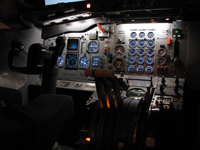
    I don't think that would work. It's hard to see in the photo, but the monitor covers 3/4 of the flap gauge mounting holes. To add to the problem, these are both dual needle gauges.

    But thanks for the suggestion anyway.

    That's what happens when you don't have the correct size monitor for the application.
    Boeing Skunk Works
    Remember...140, 250, and REALLY FAST!

    We don't need no stinkin' ETOPS!


    Powered by FS9 & BOEING

  4. #14
    Heli Builder
    Join Date
    May 2008
    Location
    Earth
    Posts
    288
    Contribute If you enjoy reading the
    content here, click the below
    image to support MyCockpit site.
    Click Here To Contribute To Our Site

    Quote Originally Posted by Michael Carter View Post
    I don't think that would work. It's hard to see in the photo, but the monitor covers 3/4 of the flap gauge mounting holes. To add to the problem, these are both dual needle gauges.
    Oh yeah now I see it on the photo. I thought they were some background lightning coming through.
    Fritz -> Helicopter Cockpit Builder
    (FSX | TH2Go | Arduino | Air Manager Avionics | CNC)

  5. #15
    2000+ Poster - Never Leaves the Sim Michael Carter's Avatar
    Join Date
    Oct 2006
    Location
    Southern Illinois, USA
    Posts
    2,887
    Contribute If you enjoy reading the
    content here, click the below
    image to support MyCockpit site.
    Click Here To Contribute To Our Site

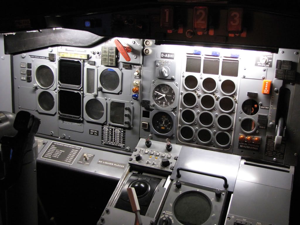
    Here's an updated photo with most of the bezels in place except for the EPR and one flap gauge.

    All of the missing panel screws have been added too.
    Boeing Skunk Works
    Remember...140, 250, and REALLY FAST!

    We don't need no stinkin' ETOPS!


    Powered by FS9 & BOEING

  6. #16
    500+ This must be a daytime job Jackpilot's Avatar
    Join Date
    Dec 2005
    Location
    MONTREAL
    Posts
    930
    Contribute If you enjoy reading the
    content here, click the below
    image to support MyCockpit site.
    Click Here To Contribute To Our Site

    I have seen recently dual needle flap gauges on ebay...??
    Just putting the real faceplates and needles would look good (better than Bitmaps)
    see if I can trace it back..

    http://cgi.ebay.com/ebaymotors/Krato...QQcmdZViewItem

    ??
    Jackpilot
    B737-700 Posky
    FS9/P.Magenta
    without PMSystem

Page 2 of 2 FirstFirst 12

Similar Threads

  1. Beech Baron Engine gauges?
    By Jordan Farmer in forum General Builder Questions All Aircraft Types
    Replies: 1
    Last Post: 09-09-2010, 06:13 PM
  2. Engine Gauges
    By mach7 in forum MyCockpit Support:
    Replies: 1
    Last Post: 08-30-2009, 01:32 PM
  3. How does one make gauges?
    By Crescent in forum General Builder Questions All Aircraft Types
    Replies: 9
    Last Post: 07-05-2009, 06:08 AM
  4. Mechanical engine gauges
    By mach7 in forum MyCockpit Support:
    Replies: 3
    Last Post: 04-29-2009, 07:25 PM
  5. How to show only 2 gauges in engine page
    By Tony in forum PM Boeing GC
    Replies: 10
    Last Post: 11-20-2008, 08:32 AM