

Results 11 to 20 of 45
-
08-17-2008, 08:57 AM #112000+ Poster - Never Leaves the Sim


- Join Date
- Nov 2005
- Location
- Ontario, Canada
- Posts
- 2,223
Guys, Originally Posted by Jackpilot

If you place a resistor in series with the capacitor you can control the speed to which the capacitor will charge. you would be required to use something like a 2500 Micro farad capacitor and try like a 10K resistor to start.
You would have some playing to do, (I am sure Mike could give you the formula), however I think you would find that it would work to your satisfaction.
Trev________________________
Trevor Hale
-
08-17-2008, 09:28 AM #12500+ This must be a daytime job


- Join Date
- Dec 2005
- Location
- MONTREAL
- Posts
- 930
Thanks Trev. will try that too.
For the moment I tried what Mike asked for and either I do it wrong or my multim is not sophisticated enough (probably) but here is what I get.
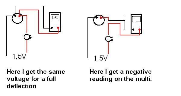
On item 2 (serie) I get a neg on the multi and a positive move of the pointer if I insert the multi on one side (pos or neg do not rmemeber) and vice versa.
Would be so nice to have those few analog gauges on the NG become alive with a little bit of ingenuity and a very thin budget.Jackpilot
B737-700 Posky
FS9/P.Magenta
without PMSystem
-
08-17-2008, 11:44 AM #13500+ This must be a daytime job

- Join Date
- Feb 2006
- Location
- Indianapolis, IN
- Posts
- 761
Allot of those gauges are D'Arsonval movements and work on VERY low current. I expieremented using 3V source and cap and resistors. IT was impossible to get smooth movement, it would bounce real bad.
-
08-17-2008, 12:27 PM #14300+ Forum Addict

- Join Date
- Feb 2007
- Location
- California, USA
- Posts
- 380
You can get a positive reading on the multimeter by reversing the leads connected to it. Originally Posted by Jackpilot
When you measured 1.5 for the voltage reading, what position was the multimeter selector switch set at?
What sort of multimeter are you using? Is it digital or a moving needle type?
-
08-17-2008, 12:35 PM #15500+ This must be a daytime job
- Join Date
- Dec 2005
- Location
- MONTREAL
- Posts
- 930
When you measured 1.5 for the voltage reading, what position was the multimeter selector switch set at?
Lowest range 15v »DC
What sort of multimeter are you using? Is it digital or a moving needle type?
Needle...think I need a better one.Jackpilot
B737-700 Posky
FS9/P.Magenta
without PMSystem
-
08-17-2008, 04:36 PM #16300+ Forum Addict

- Join Date
- Dec 2005
- Location
- Gravenhurst, Ontario
- Posts
- 446
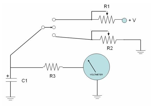
A while back, I posted this circuit. The gauge could be there instead of a voltmeter as shown in circuit. The Values for R1-R2 & C1 depend on the time constant you want to achieve. Also, instead of the switch, there could be relay switches instead so that the whole operation could be automatic when the power is applied ore removed.
Here is an explanation from Wikipedia:
In an RC circuit, the value of the time constant (in seconds) is equal to the product of the circuit resistance (in ohms) and the circuit capacitance (in farads), i.e. τ = R × C. It is the time required to charge the capacitor, through the resistor, to 63.2 (≈ 63) percent of full charge; or to discharge it to 36.8 (≈ 37) percent of its initial voltage. These values are derived from the mathematical constant e, specifically 1 − e − 1 and e − 1 respectively.
A convenient short-cut is that the same formula works if R is in megohms (MΩ) and F is in microfarads (μF).
Maurice
-
08-17-2008, 06:28 PM #17500+ This must be a daytime job
- Join Date
- Dec 2005
- Location
- MONTREAL
- Posts
- 930
I assume that the R1 circuit is for ON (gauge spooling up) and R2 for OFF and spool down
R1 and R2 being Pots
Acordingly in T= R X C
R= R1+R3 or =R2+R3 if spool up and down are the same duration.
Correct ?Jackpilot
B737-700 Posky
FS9/P.Magenta
without PMSystem
-
08-17-2008, 06:45 PM #18300+ Forum Addict
- Join Date
- Dec 2005
- Location
- Gravenhurst, Ontario
- Posts
- 446
Originally Posted by Jackpilot
No, R3 does not enter in the RC picture and should be very high resistance. You may have to experiment with the value but the higher the better (try 10 Megohms) . It is just there so that C1 does not discharge via the gauge (I'm assuming the gauge does not have a high resistance value like a voltmeter has).
So RC should be R1 x C1 for spool up and R2 x C1 for spool sown.
Maurice
-
08-17-2008, 08:50 PM #19300+ Forum Addict
- Join Date
- Feb 2007
- Location
- California, USA
- Posts
- 380
Were you able to make the current reading with the multimeter leads reversed? Originally Posted by Jackpilot
If we know the voltage across the gauge and the current through it at full scale we can calculate the gauge resistance and know its sensitivity so we can select the right circuit values.
-
08-18-2008, 10:19 AM #20500+ This must be a daytime job
- Join Date
- Dec 2005
- Location
- MONTREAL
- Posts
- 930
Yes. ....still reads 1.5 but the gauge needle moves 1/10 of its travel and even by turning the pot (100K) full , the gauge pointer does not move much further. Originally Posted by Mike.Powell
??Jackpilot
B737-700 Posky
FS9/P.Magenta
without PMSystem

 Reply With Quote
Similar Threads
-
Latest picture and update on my real 727 engine gauges working
By 737NUT in forum Interfacing Real Aviation PartsReplies: 11Last Post: 07-31-2011, 11:45 AM -
Real VSI+$40+1hour=Working real gauge!
By 737NUT in forum Interfacing Real Aviation PartsReplies: 6Last Post: 01-11-2010, 01:35 PM -
AFT OVH - PMSys 122
By Tony in forum PMSystemsReplies: 9Last Post: 03-16-2009, 06:35 AM -
Real 1.5" yaw damper gauge
By Jackpilot in forum General Builder Questions All Aircraft TypesReplies: 8Last Post: 10-14-2008, 07:45 PM -
One CPU for FS9 + GC + CDU + MCP + pmSys + pmInst
By Greg Kernaghan in forum PM General Q & AReplies: 4Last Post: 01-22-2006, 04:38 AM


Candid connections: Platform for casual relationships Live Women Prime Сasual Dating
Super Сasual Dating - Genuine...