

Results 101 to 110 of 251
Thread: burning question - HSI?
-
07-24-2008, 11:24 AM #10175+ Posting Member


- Join Date
- Jul 2008
- Location
- Brisbane, Australia
- Posts
- 83
OK my brain hurts - but the drive shafts are in. I had to change the gears because they wouldn't fit. 32 on the (48 steps/rev) stepper drives a 48 on the idler for 2:3, a 12 on the other end of the idler drives the 120 for 1:10. Total 1:15, 0.5deg/step for all 4 rings. You can see the dual-axle shaft on the left of the instrument drives the front two rings, and the other on the right drives the rear two.
I had to remove the glideslope servos as there's just no room. Maybe we could do it with LED bars? Can someone get me dimensions on a 5- or 10- LED bar?
Remaining is the axle and brushes for the CDI assembly and the circuit board. Then: over to you guys
If anybody has 3dsmax9 please let me know, I need you to inspect the model to pick up any errors. Where's Mr Powell when you need him Couldn't have done this without inspiration and information from your excellent book sir.

Last edited by Matt Olieman; 07-24-2008 at 02:33 PM.
-
07-24-2008, 11:35 AM #102300+ Forum Addict

- Join Date
- Feb 2007
- Location
- California, USA
- Posts
- 380
Looks good to me. Originally Posted by ruprecht

VERY interesting project!
-
07-24-2008, 03:01 PM #103Executive Vice President, MyCockpit

- Join Date
- Oct 2005
- Location
- Ocala, FL USA
- Posts
- 2,884
Please folks
Upload the photos in the gallery and link them in the forum rather then outside of MyCockpit.org. Otherwise it takes forever to load up a page.
I've moved all the CAD drawings to MyCockpit.org. NOW LOADS INSTANTLY!!!!
Matt O.
-
07-24-2008, 04:36 PM #10475+ Posting Member

- Join Date
- Dec 2006
- Location
- Russell Island Australia
- Posts
- 127
Hi guys:
Sorry for my absence. I'm in the middle of selling my boat and there's work to be done that keeps me out all day. I'll be offline for the rest of the weekend probably.
Whew!!! I miss one day and you guys have filled three pages of stuff...GREAT WORK!!!
Seriously here's some things I see.
I see that you've added a fourth gear and stepper. If we can get rid of it I think it would be better from a reliability/simplicity point of view. I agree with the guy who designed the blackbird "Simplicate and add lightness"
The washers for the retainers/stepper can be easily custom made. Also we can make them from delrin which will make them slippery and smooth.
Please let's don't go to 4". The only thing that I think would push us there is accomodating lots of steppers and I'v already aired my opinion on that.
Reed switches are 13mm long and 2mm diameter with axial leads. The exit of the leads is VERY fragile so allow about 20mm width total to keep the bend in the leads away from the body.
Sourcing parts from the US. I have a friend in Texas who is quite willing to source stuff and ship it for me. I'm sure that if we offered him an HSI, he'd fall all over himself to help.
I only have Protel99 for PCB, but I see Andy has put his hand up for that. Good one Andy.
Don't buy stuff from Futurlec. They are honest, but slow. Also they only seem to deal with runout stock so supply may not be guaranteed.
For stepper drivers for small steppers, it's hard to go past the FAN8200 from JAMECO. At 80 odd cents they're cheap as chips They can drive unipolar or bipolar steppers so they're very versatile. Unfortunately, they're through hole devices so if we need 4 on a board, that's a lot of real estate. Another reason to get rid of that extra gear/stepper.
Ruprecht: What can I say about your drawings. Mate I'm just speechless in awe. I do have a suggestion though. You could squeeze some space out from between some of the gears and maybe bring back the glideslope servo. I think also that the GS could be done with one servo, we might just have to make a fiddly bit of metalwork for the arms. But that's OK. I really think the glideslope capability is essential.
*EDIT* Instead of squeezing space out from between the gear plates, maybe if you added just a little space forward of the plate in front of the steppers, the GS servo(s) could go there??
Finally, I just don't believe the work you guys have done on this. I can hardly wait to get started on the parts.
*EDIT* Ruprecht, I don't think we need the fourth gear. The course pointer will ride on the CDI plate.
*EDIT* I just had another idea for the GS pointers. mount them on cables and make them slide up and down. Put a pulley at the top and bottom and drive the cable from the servo. Then the servo can be mounted in any orientation.Regards: Scott Hendry
www.scotthendry.com
-
07-24-2008, 07:24 PM #10575+ Posting Member
- Join Date
- Jul 2008
- Location
- Brisbane, Australia
- Posts
- 83
Guys, a quick explanation of a few things:
4 rotating elements are required. Compass card, heading bug, RMI needle, CDI assembly.
I could dispense with the fourth (CDI) gear, but what would I replace it with? In the end, the assembly must rotate. As it stands now, all 4 rotating elements work exactly the same way, same gearing, same everything. I agree with "simplicating" (did Dubbya work on the SR71? ) but IMHO making one rotator work differently is "complificating" Accept that it means more work for our esteemed gear cutter though
Re Delrin, mate do you have an Australian source? I've had no answer from Aircraft Spruce's local distributor.
Agree on avoiding 4" unless it becomes impossible otherwise. Not least because of the redesign work required!
re board space, the only circuit board that will be tight will be the swinging CDI board. the rest we can split over multiple 3"x3" boards if necessary. I'd prefer to use the RS422 architecture from MikesFlightDeck rather than depending on any specific manufacturer's control hardware, if that's at all possible?
I'll pick up some reed switches today hopefully, just so I have one handy for prototyping.
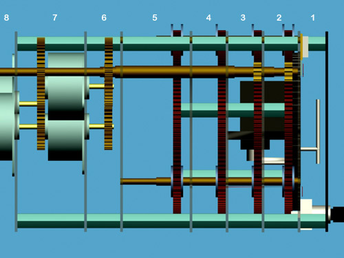
Referring to the numbered sections in the pic above, I agree we could probably save some space in sections 2, 3 and 4 now that we've dispensed with the optos. However until we've figured out the position sensing and are sure there's enough room, I'll leave it as is. I can always compress things later, but I'd hate to do it now and have to undo it because of unforseen requirements.
I think it's important to keep section 1 as shallow as possible to maintain the "look" of the instrument. Obviously there's a minimum depth dictated by the CDI needle, which in turn is related to the CDI indicator arc radius, dictated by how far back the CDI servo is. 3/8" will do for now
Sections 2,3,4 and 6 are 1/2" deep. Section 5 and 7 are 1" deep. Section 5 is reserved for the swinging circuitry mounted on the back of the CDI gear (gear 4), to be modelled when my mouse shoulder stops hurting!
The problem with a single arm for both glideslope indicators is that the arm must, at some point, stretch horizontally across the width of the instrument with some range of vertical movement. I'd welcome suggestions, but I can't figure out where to fit it unless you move it right back beyond section 8, in which case flexion in the armature will give us accuracy problems. A LED bar is a "simplicated" solution and not one for the purist, but it's an option. Possibly as you say Scott, extending section 5 to 2" might give us enough room. The pulley idea is an interesting one, I had thought along similar lines with a toothed belt and worm gear, but dismissed it as too complex. Maybe you could sketch something and I can then model it?
Thanks for the kind words. I am trying very hard to accommodate all suggestions, I understand this is a community project and am resisting the temptation to just design it the way I want! Part of the reason for doing CAD is that it reveals things that just won't physically work, and much of the trial and error I go through when modelling isn't visible in the end result, but many lessons are being learned and I'm trying to document them here. Please be patient with me, I'm doing this around my day job and my young family
-
07-24-2008, 08:19 PM #10675+ Posting Member
- Join Date
- Jul 2008
- Location
- Brisbane, Australia
- Posts
- 83
Matt, thanks for the tip on the images. I was hosting them on my own Apache server hanging off my broadband, so no wonder it was slow for y'all! And no wonder my bandwidth got hammered last night when you featured the post on the front page

Cheers
-
07-24-2008, 08:24 PM #1072000+ Poster - Never Leaves the Sim

- Join Date
- Nov 2005
- Location
- Ontario, Canada
- Posts
- 2,223
I would like to introduce you to the Power of MyCockpit.org LMAO.. Originally Posted by ruprecht
 ________________________
Trevor Hale
-
07-24-2008, 09:16 PM #1081000+ Poster - Fantastic Contributor

- Join Date
- Jun 2006
- Location
- Oahu, Hawaii
- Posts
- 1,236
WHOA! I get a few hours sleep and we lose the optical sensors! How did that happen? And why?
-
07-24-2008, 09:21 PM #10975+ Posting Member
- Join Date
- Jul 2008
- Location
- Brisbane, Australia
- Posts
- 83
They are too big (causing sect 2,3,4 to be deeper than necessary) and the interrupter flags conflict with the driver shaft. Reed switches and magnets are a neater solution I reckon?
-
07-24-2008, 09:27 PM #1101000+ Poster - Fantastic Contributor
- Join Date
- Jun 2006
- Location
- Oahu, Hawaii
- Posts
- 1,236
Ok, so we get rid of the interupter flags and drill a hole in the gears, then straddle the sensors over the gears themselves. Uses less room between gears than the flags, is more accurate, and we can test for an 'open' instead of a 'close' to get our reading.
Its the simplest solution. If we have to lengthen the case by an inch, then so be it. We knew going in this would be a larger than normal instrument, and we NEED some kind of sensors. Mounting magnets and reed switches while it sounds cool, is needlessly complex to my thinking. There is the issue of mounting the magnets on the gears themselves in a way that over time they do not get dislodged or even fall off completly. Drilling the hole is easy and simple.
Try putting them in the way I suggest and see what we get.

 Reply With Quote


Free connections, find your partner with no obligations Real-life Girls Exemplary Сasual Dating
Super Сasual Dating - Verified...