

Results 11 to 17 of 17
-
01-03-2008, 10:54 PM #112000+ Poster - Never Leaves the Sim


- Join Date
- Oct 2006
- Location
- Southern Illinois, USA
- Posts
- 2,887
Thanks for the info. That's pretty neat the way Gables designed the buttons on that head. It does look like there's bulbs in there.
The reason I go from 5VDC to 12VDC if I can't get any light out of the plate is that I'm scared I may have missed something during the probe and don't want to hit it with 28(24)VDC if in fact they really are 5VDC.
Although 12VDC might burn them up too, it may give me a half second longer to remove the probes.
You were explaining the bulb arrangement the different manufacturers use to light the plates; the radar display I just received is as you described with the bulbs actually being mounted in the equipment. The Collins 614's are the same way. Or was it the HF radio? Now I can't remember. Boeing Skunk Works
Remember...140, 250, and REALLY FAST!
We don't need no stinkin' ETOPS!
Powered by FS9 & BOEING
-
01-06-2008, 06:59 PM #12Our new friend needs to reach 10 posts to get to the next flight level
- Join Date
- Dec 2007
- Location
- Ft. Worth, TX
- Posts
- 9
Pictures of my project
All,
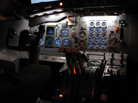
Here are the pictures I promised; my restoration of a 727-100 instrument panel along with Overhead Panel and Throttle quad.
Rick
-
01-06-2008, 07:31 PM #13Executive Vice President, MyCockpit


- Join Date
- Oct 2005
- Location
- Ocala, FL USA
- Posts
- 2,884
Fantastic Rick, what a wonderful project, excellent looking equipment, congratulations

-
01-06-2008, 09:07 PM #142000+ Poster - Never Leaves the Sim
- Join Date
- Oct 2006
- Location
- Southern Illinois, USA
- Posts
- 2,887
Very nice. Good to see another 727 instrument panel on this forum. Looks like home to me! Originally Posted by 3-Holer

What is the module between the anti-skid and Flight Control Warning Test module in the left bay of the overhead?
If you need a -100 landing gear panel (less acuator) let me know. I might have a contact with one that is particular to the -100 series. I know the light arrangement is different for that varient.Boeing Skunk Works
Remember...140, 250, and REALLY FAST!
We don't need no stinkin' ETOPS!
Powered by FS9 & BOEING
-
01-07-2008, 01:44 AM #15Our new friend needs to reach 10 posts to get to the next flight level
- Join Date
- Dec 2007
- Location
- Ft. Worth, TX
- Posts
- 9
The module above the Anti-Skid panel is "GPWS--OFF, NORM". [GPWS=Ground Proximity Warning System]. The switch cover is typically safety-wired (copper wire) to the "NORM" position. When in the "OFF" position, the GPWS is disabled and allows abnormal landings, that involve flap problems or zero-flap, to occur without the GPWS warning going off during the approach (flap position is one of several parameters monitored by GPWS). This panel is also sometimes located elsewhere on the overhead and, on some aircraft, it can be found on the lower Flight Engineer (FE) panel. There is a "GPWS" amber light that indicates system problems on the "Door Warning" light panel located on the lower FE panel as well. When a GPWS dynamic warning is tripped, the pilot/co-pilot have their own "Pull Up" and "Below Glideslope" indicators on their respective panels that will illuminate accordingly along with the aural warning.
Thanks for mentioning it, but I already have the -100 peculiar landing gear panel plus light module but did not include it in the picture due to it being stored in a box at the moment (I also have the gear handle itself). At the moment, I do not have the physical space in the apartment to properly set-up my instrument panel until I move to a bigger place, probably later this year. Right now, I work on the panels and other stuff individually as I get them ready for integration into a full-blown panel set-up sometime in the future. I also have the fire handle assembly and glareshield, but those are stored as well.
I temporarily put the panels against the wall for the purpose of getting the pictures, so I could show them here.
Rick
-
01-07-2008, 03:34 AM #162000+ Poster - Never Leaves the Sim
- Join Date
- Oct 2006
- Location
- Southern Illinois, USA
- Posts
- 2,887
That must be particular to the -100 series. The -200 GPWS "GPWS--OFF, NORM" is controlled only on the FE panel or by a CB. I'd have to check which P-panel it's on. The -200 includes a test panel with a single push-button and Korry indicator and the failure annunciator can be found on some models integrated with the overhead speaker panel. On others, it's on the left (right) MIP. I guess it depends on when it was built and what the customer specified.
The PULL UP and BELOW G/S warnings are located in various locations on the -200. Mine are located just above the right side of the A/S indicator, though I have seen them farther over on the left panel where my windshear indicators are and below the VSI on others.
It's like trying to re-build a '70 455 Stage1 Buick GS from the ground up without a build sheet.Boeing Skunk Works
Remember...140, 250, and REALLY FAST!
We don't need no stinkin' ETOPS!
Powered by FS9 & BOEING
-
01-08-2008, 10:51 PM #17Our new friend needs to reach 10 posts to get to the next flight level
- Join Date
- Dec 2007
- Location
- Ft. Worth, TX
- Posts
- 9
You are so right regarding the never-ending configurations of various items on the 727! Between the various models, different customer configurations, and the changes made by the new owners as the aircraft changed hands, it does become hard to nail down one standard cockpit set-up. Then there is TWA. They just had to be different so they went as far as re-designing many of the standard 727 modules; this can be readily seen by looking at a TWA Flight Engineer panel; many changes compared to standard panels.
My panel came from a 727-23, which was intially delivered to AA. I intially tried to configure the panel and all instruments to the same type used by AA. I have an AA Flight Manual that is specific to these aircraft (by registration number) so have an excellent source for what the original panel had. Unfortunately, not all the original components are available. For example, the airspeed indicators are not like the originals because they are combination airspeed/mach meters. The original configuration had separate airspeed and mach indicators; this explains the instrument covers to the immediate left of the airspeed indicators, which is where the mach meter was installed. Tracking down the 727-specific surface position indicator was another long wait; there are several versions of this instrument as well....it never stops!!!
I hit pay-dirt a few years ago when I came across the True Airspeed (TAS)/Static Air Temperature (SAT) indicator that is mounted to the left of the co-pilot's RMI; this is a very unique design indicator that was used on many AA aircraft, including their 727-23 and 707's. Needless to say, I was very happy to find this rare gem!
I still need the combination "Pull Up" and "Below Glideslope" lens; the ones installed (lower right corner of each panel) do not have those words. I may have to make those myself.
Anyway, as they say, "a work in progress"...
Rick
One unfortunate problem is that the center panel did not come from the same aircraft as the left/right panels!! It is close but is configured differently then the 727-23.

 Reply With Quote
Similar Threads
-
For you X plane folks
By Joe Cygan in forum General Builder Questions All Aircraft TypesReplies: 5Last Post: 09-24-2010, 10:55 PM -
what do you folks think
By Mr. Midnight in forum Computer Hardware SetupReplies: 8Last Post: 10-11-2008, 10:14 AM -
Hello Folks
By KenD in forum Welcome to MyCockpit New here? Introduce Yourself!Replies: 4Last Post: 11-01-2007, 09:02 AM


Looking for fun companions for travels and adventures? Authentic Ladies Premier Сasual Dating
Top-notch Сasual Dating -...