

Results 21 to 30 of 53
Thread: Interfacing real 727 eng gauges
-
12-29-2009, 11:35 AM #21500+ This must be a daytime job


- Join Date
- Feb 2006
- Location
- Indianapolis, IN
- Posts
- 761
Re: Interfacing real 727 eng gauges
Could i also use the PIC to drive my EGT gauge? I did some testing on it, looks like 0 to 100mV will do ion the signal side.
Rob
-
12-29-2009, 12:21 PM #22500+ This must be a daytime job
- Join Date
- Feb 2006
- Location
- Indianapolis, IN
- Posts
- 761
Re: Interfacing real 727 eng gauges
Finally got a picture to post for everyone to see.
-
12-29-2009, 06:53 PM #23300+ Forum Addict

- Join Date
- Feb 2007
- Location
- California, USA
- Posts
- 380
Re: Interfacing real 727 eng gauges
I think we could use a very similar approach. Originally Posted by 737NUT

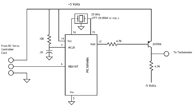
Here are my current thoughts on the RC servo to tach adapter:
This is based on using a PIC 16F648A. They're cheap and I've got a couple on hand to play with. We connect the RC servo control line to the external interrupt input on the PIC. We clear PIC timer2 which is 16 bits wide. We enable rising edge interrupt on the int input. Whe we see an interrupt we turn on timer2 and enable a falling edge interrupt on timer2. When we get an interrupt we turn off timer2. The timer2 contents is now a measure of the RC servo control pulse width.
The pulse width varies between about 900 and 2100 microseconds. We subtract a number from the timer2 count to remove the 900 microsecond offset. We now have a number from zero to something proportional to 1200 microseconds. This is now the number we want to control the frequency of the output tachometer signal.
Let's skip ahead to the ouput signal. This is a square wave that varies in frequency between 0 and 77Hz. We'll make this by setting PIC timer1 to interrupt about every 26 microseconds. Each time it interrupts we'll decrement a variable by 1. When it hits 0 we'll complement the tachometer output signal and reset the value of the countdown variable.
The value of the countdown variable is related to the period of the tach control signal. The value we made using timer2 is proportional to the frequency. To get the countdown value we'll have to divide the timer2 value into a constant value. Its value will depend on how we clock the timers.
The arithmetic operates on numbers larger than 255 so the code will deal with multi-byte variables.
Here's the rough hardware design the code will run on. We should be able to pull power (+5) from the RC servo controller card. I'll add the -5 volt inverter later.
Totally off topic: I saw Avatar http://www.avatarmovie.com/ yesterday. Wow! I would really like to find a "Sampson" helicopter flight model and some Pandora scenery.
-
01-04-2010, 12:30 AM #24300+ Forum Addict
- Join Date
- Feb 2007
- Location
- California, USA
- Posts
- 380
Re: Interfacing real 727 eng gauges
A brief update:
I've written PIC firmware to convert a standard 0.9 to 2.1 millisecond RC servo control pulse to a 0 to 77 Hz square ware. It more or less works in the PIC assembler simulator. Next step is back to cobbling hardware together.
-
01-04-2010, 02:35 AM #2575+ Posting Member

- Join Date
- Jan 2008
- Location
- FNQ Australia
- Posts
- 126
Re: Interfacing real 727 eng gauges
is this thread in english  ?
?
Great work guys. That gauge looks excellent when fired up... you realise we will all want them ...
-
01-04-2010, 10:55 AM #26500+ This must be a daytime job
- Join Date
- Feb 2006
- Location
- Indianapolis, IN
- Posts
- 761
Re: Interfacing real 727 eng gauges
Sounds good Mike. I'm trying to see if i can program the pic thru my OC card. What part number PIC do you use? Want to see if it is the same as the one they use as i have a spare one.
-
01-04-2010, 02:13 PM #27300+ Forum Addict
- Join Date
- Feb 2007
- Location
- California, USA
- Posts
- 380
Re: Interfacing real 727 eng gauges
It's a PIC16F648A. Originally Posted by 737NUT
-
01-04-2010, 02:39 PM #28500+ This must be a daytime job
- Join Date
- Feb 2006
- Location
- Indianapolis, IN
- Posts
- 761
Re: Interfacing real 727 eng gauges
How many gauges can one PIC drive? Thanks for the info and again for all the help. The gauges have been working well on the bench over the holidays. No issues so far. Also, i forgot to mention that the servo card has 1023 step resolution but that shouldn't affect the the PIC programming correct.
-
01-04-2010, 04:52 PM #29300+ Forum Addict
- Join Date
- Feb 2007
- Location
- California, USA
- Posts
- 380
Re: Interfacing real 727 eng gauges
It's one gauge per PIC. Jameco sells them for $2.25 each.
The bulk of the firmware can be used for the EGT adapter, assuming you plan on using the OC servo card for the EGT as well. The portion of the firmware that generates the square wave output can be replaced by code to generate a 0 to 100% pulse width modulated output. Perhaps the way to go is to put both functions in the firmware and have the PIC choose which to do based on whether an input pin is high or low at reset time.
-
01-06-2010, 11:29 PM #30300+ Forum Addict
- Join Date
- Feb 2007
- Location
- California, USA
- Posts
- 380
Re: Interfacing real 727 eng gauges
Okay, the PIC is doing its thing. I'm simulating an RC control pulse and the PIC is making square waves with a frequency that varies linearly with changes in the servo control pulse width.
What's our next step? Can you program a 16F648A from a hex file? Should we port the code to a different PIC? You want me to program them?

 Reply With Quote
Similar Threads
-
Interfacing a real GPS with FSX?
By Shawn in forum General Builder Questions All Aircraft TypesReplies: 7Last Post: 02-21-2009, 01:39 AM -
Interfacing real radios with SIOC
By sja in forum Interfacing Real Aviation PartsReplies: 6Last Post: 02-12-2009, 10:32 AM -
Interfacing real radios with SIOC
By sja in forum I/O Interfacing Hardware and SoftwareReplies: 6Last Post: 02-12-2009, 10:32 AM -
ideas on interfacing real 737 start switches ?
By dnoize in forum I/O Interfacing Hardware and SoftwareReplies: 5Last Post: 08-20-2008, 08:47 AM -
interfacing real yoke trim switch with IO cards????
By steve diamond in forum I/O Interfacing Hardware and SoftwareReplies: 3Last Post: 08-29-2006, 04:23 PM


Search Pretty Girls from your town for night
JeeHell FMGS on a remote Computer