

Results 11 to 20 of 26
Thread: 727 MIP dimensions
-
06-13-2011, 05:35 PM #11150+ Forum Groupie


- Join Date
- Jun 2009
- Location
- Norway
- Posts
- 173
Re: 727 MIP dimensions
Hi BSD
I've tried to e-mail Joe, never heard back from him. Looks like I'm getting some dimensions from a different source though!
I'm using FSX, and I do have the CS 727 Captain. Lovely plane, but I'm not sure how well it'll work with a cockpit. I'm waiting for the DreamFleet 727 FSX update, if that comes with a 2D panel I might be able to use the guages from that. I've played around with the guages from the Richard Probst 727 panel in FS panel studio, so I have an Idea of how I'm going to set up the guages behind the panels. The CS 727 only comes with a VC, and I've not been able to display the guages in FS Panel Studio unfortunately.
As far as -100, -200 or cargo, I don't know. If I'm at all able to recreate a home cockpit that vagely resembles a 727 I'll be happy for starters! I think the -200 is my favourite.
Tor-Olav
-
01-08-2012, 10:09 AM #12150+ Forum Groupie
- Join Date
- Jun 2009
- Location
- Norway
- Posts
- 173
Re: 727 MIP dimensions
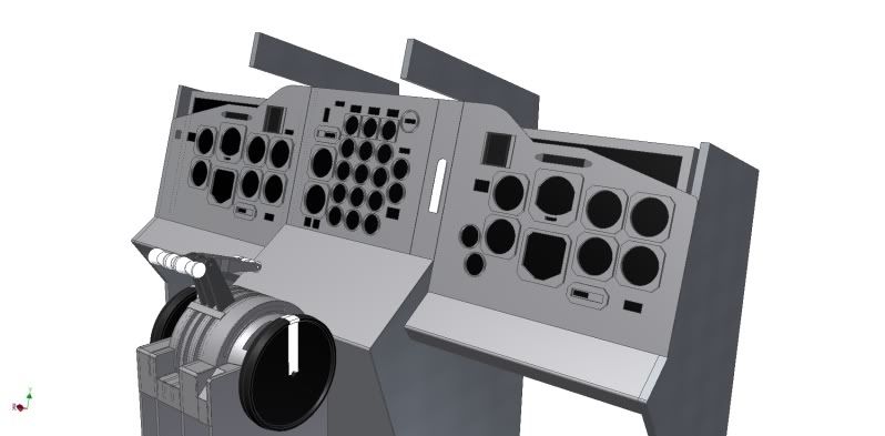
Well, it's been a while since the last update. I'm finally happy with my MIP panels. After countless hours of studying photos, searchin the net for info and making quite a few guestimates I'm ready to have the panels cut. I've had to make a few compromises to be able to place all the guages and annunciators within my LCD's, but I don't think anyone will notice!
OH panel, autopilot module and a flight director from a real 727 should arrive tomorrow. Let the fun (and frustration I'd imagine) begin!
-
01-09-2012, 03:19 PM #13150+ Forum Groupie
- Join Date
- Jun 2009
- Location
- Norway
- Posts
- 173
Re: 727 MIP dimensions
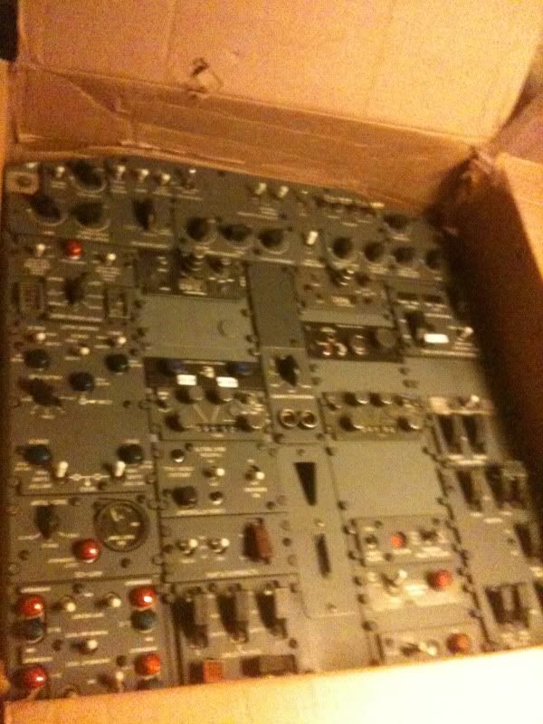
A few items arrived today!
OH panel
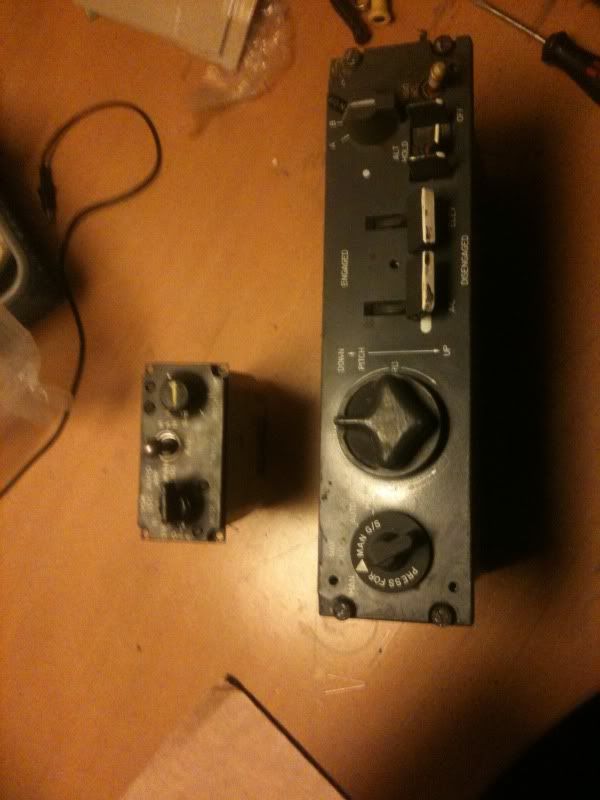
Sperry-50 Autopilot module and Collins flight director
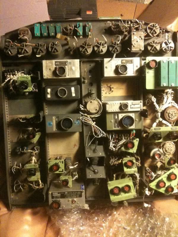
Back side of the OH. I'm going to have some job interfacing this stuff:O Any tips and tricks is very much appreciated!
-
01-11-2012, 09:24 AM #1425+ Posting Member
- Join Date
- Jun 2008
- Location
- Berlin, Germany
- Posts
- 49
Re: 727 MIP dimensions
Congratulations.
For the wiring: the OH is pretty straight forward: remove the cannon plug holders and cutnthe cables. THen you can easily track the cables of the individual sub-panels the the respective switches. Usually you have more than one cable pair. Find the pair that belongs together (electrical connection when switched on) and connect the cables to your I/O card.
For the Lamps you have three cables: two to light the bulb and one for the push-to-test option. Connect the cables to your output cards, for the PTT cables you can collect them and connect the together to a permanently "on" output on the same output card (they share the GND with the "real" cable of the bulb. Consider replacing the bulbs by LEDs with the same base (cost approx 2,50 @ Conrad). The colour is colder (less yellow-isch), but the bulb does not get that hot and it will use considerably less electricity and the output card might be limited (I use OpenCockpits and the only work up to (I think) 1,5 Amps).
Good luck & enjoy,
Florian
-
01-12-2012, 02:38 AM #15150+ Forum Groupie
- Join Date
- Jun 2009
- Location
- Norway
- Posts
- 173
Re: 727 MIP dimensions
Thanks LH784.
I've had a closer look at the OH, and I have a rough idea of how I'm going to interface lights and switches. I tried o connect all the backlights to a 19V power supply and they all lit up. I'm not sure about how to connect the rheostats though. I thought I'd connect all the cockpit lighting directly to a power supply via the rheostat switches on the overhead.
Do the LED bulbs you mention still operate on 28V or are their voltage lower? I also thought of getting a OC output card, do you connect your power supply to this card?
The Sperry-50 unit is probably going to be the hardest piece to interface. Not sure if I can make alle the solenoids kick in and release in the right places etc.
Thanks again for your help.
-
01-12-2012, 06:21 AM #1625+ Posting Member
- Join Date
- Jun 2008
- Location
- Berlin, Germany
- Posts
- 49
Re: 727 MIP dimensions
Hi,
be careful with the backlights. I power mine @ 5 V !
What I do is use an old PC power supply and really thick cables since the bulbs drw quite a bit of current. Then I regulate the backlighing using a relais. So it'sjust on or off. I don't know how the rheostats work, the compass control seems to be a potentiometer, the rest rheostats, but I cannot measure any variable resistances. So I will stick with on/off. What I want to do is replace the rheostats with potentiometers, so I can turn the know. I will use the poti as a switch - high resistance => switch open, low resistance => switch closed, that will work via my I/O card and drive my relays via the USB Output card. But if oyu find out how to use the rheostat, I'd be happy to know how.
For the bulbs: I use Best.-Nr.: 725842 - 62 from
http://www.conrad.de/ce/de/product/7...12376&ref=list
There is also a 12V version. I am not sure which ones are more suitable. The 12 V can be driven by a PC power supply but will draw a higher current...I use the 24V version. And yes, I connect a 24V power supply to that card (I current have got three of them, they also operate my relays).
When I first opened my AP controller I tested 12V for the solenoids and it seemed to work, but I have not yet really started to interface it. But I think it should be possible to do it via relays, too.
Good luck and keep us updated.
Florian
-
01-12-2012, 09:40 AM #17150+ Forum Groupie
- Join Date
- Jun 2009
- Location
- Norway
- Posts
- 173
Re: 727 MIP dimensions
Ok, thanks for the heads up! I thought all the lights in the OH panel originally operated @28V! I'll see if i can find a 5V supply somewhere.
What kind of cockpit are you building?
-
01-12-2012, 03:36 PM #18150+ Forum Groupie
- Join Date
- Jun 2009
- Location
- Norway
- Posts
- 173
Re: 727 MIP dimensions
Hmmm, I'm a bit confused now. I tried to hook the panels up with 5V and absolutly nothing happens. I then tried 12V and I get a very weak illumination.
-
01-13-2012, 04:21 AM #1925+ Posting Member
- Join Date
- Jun 2008
- Location
- Berlin, Germany
- Posts
- 49
Re: 727 MIP dimensions
Well, me too. So far, the only item with backlighting different from 5 V is in my transponder, which needs 24/28V, the rest is 5V (Overhead, Nav/Com, FE panel...).
For me, the usual way is to test 5V, if nothing works, step up to 12V, then 24V. This way I hope no to smoke up my parts.
If 5V don't work for you, then it might be different with your special panel. But nevertheless, I think it is worth "working up the voltages"
I am building a 727.
Regards, Florian
-
01-13-2012, 05:34 AM #20150+ Forum Groupie
- Join Date
- Jun 2009
- Location
- Norway
- Posts
- 173
Re: 727 MIP dimensions
Thanks, I did try 5v first then 19. I'm sure it is 5v though, it says so on the back of the panels:/ I need to find a new powersupply, Maybe the one I have doesn't deliver the amps required to light the panels.
Cool that there are others building 727's How far are you into the build? Do you have a thread in here?
Tor-Olav

 Reply With Quote


Pretty Womans in your city
Find Sexy Womans from your city...