

Results 81 to 90 of 211
Thread: Spitfire IX Project
-
07-08-2009, 12:01 AM #81150+ Forum Groupie


- Join Date
- Jun 2008
- Location
- South West, Western Australia
- Posts
- 245
Re: Spitfire IX Project
I finally decided to take a day off work yesterday and get most of the finishing touches on the panel. The Hand drilling and filing is a serious PITA but I was determined to at least have a go. All things considered I think it went quite well.
The original wood mock up.

A start on the metal versions.

The metal drilled, cut and filed to get the basic patterns.


The first test fit of some of the instruments and panel fittings. I have painted the BFP and am happy with the textured finish. Part of it didnt take well though and I tried to patch it. Not 100% successful but a strip down and re-paint will be last on the list as it isnt too noticeable and I have a lot of other fish to fry. The drilled screw holes for the instruments in the main panel still need to be cleaned up on the reverse, so none of the small stuff on that panel has been fitted yet but I dont anticipate any real problems. I also still have to get together with Chris and his laser cutter soon to cut the Oil Pressure Gauge and Ammeter dummies, the U/C Indicator and some faces for the new twin needle gauges that have now arrived. One twin will be used for Oil and Fuel Pressure (unfortunately this will be an extra round gauge that is not on the original panel) and the other will have two identical graduated scales marked as Brake Pressure with one needle indicating Brake Pressure and the other scaled off EGT to use for adjusting mixture on the A2A Spitfire 1A (FSX only has an overall brake pressure figure, not one for left and one for right).

A real panel being restored and at a similar stage.

Finally, the detail of the Blind Flying Panel stand-offs I decided to leave the main panel as complete as possible for structural integrity so rather than cut extra volume out of the middle and use brackets, I used tabs left on the panel as mounting holes for bolts. The original uses brackets with rubber boots mainly to cut down vibration on the six primary flying instruments which are particularly susceptible to it.
A couple of small adjustments still necessary to stop the PCBs shorting on the aluminium frame. I havent powered it up yet for that reason.

Hopefully the next step is to get the main panel finished and primed for painting.
Darryl"Tony"
In memory of Flt Lt Tony Hill who, on 5 December 1941, at the request of Doctor R V Jones, successfully photographed a small "Würzburg radar" at Bruneval on the French coast. This from a height of only 200 ft, at high speed, under fire and from a camera mounted obliquely behind the cockpit.
-
07-08-2009, 08:32 PM #82MyCockpit Support Staff


- Join Date
- Nov 2005
- Location
- Perth, Western Australia
- Posts
- 1,415
Re: Spitfire IX Project
It looks sweet Darryl, a great match for your nearly completed flight controls, end of next week maybe!!!
Gwyn
737NG using Prosim737, Immersive Calibration Pro, Aerosim Solutions motorized TQ & cockpit hardware, CP Flight MCP & FDS SYS1X, SYS2X & SYS4X, FDS PRO FMCs, AFDS units & Glarewings, Matrix Orbital ELEC display, Pokeys Landing & Cruise alt display, Buttkicker Gamers, 3 x BenqMW811ST projectors with a Matrox Th2Go
http://www.aerosimsolutions.com.au
Supporter of MyCockpit.org, please join me in donating!!!
-
07-17-2009, 05:52 AM #83MyCockpit Support Staff
- Join Date
- Nov 2005
- Location
- Perth, Western Australia
- Posts
- 1,415
Re: Spitfire IX Project
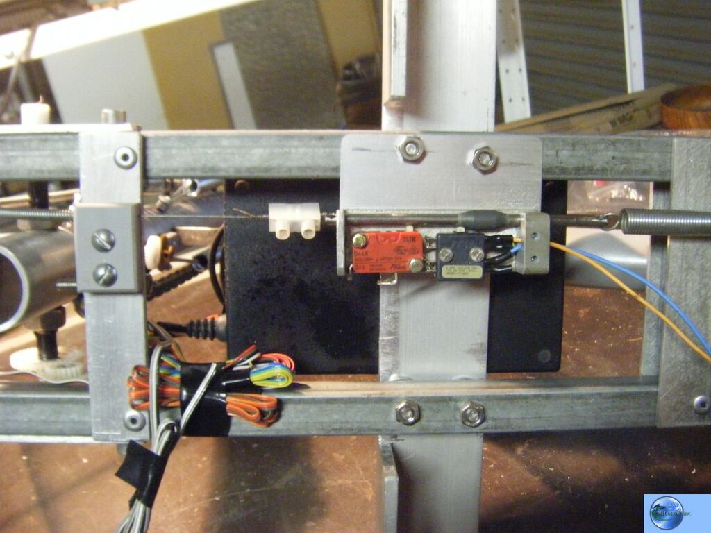
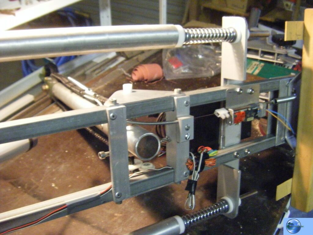
Hi all, here are more progress pics of Darryl's flight controls


GwynLast edited by Westozy; 07-17-2009 at 06:00 AM.
737NG using Prosim737, Immersive Calibration Pro, Aerosim Solutions motorized TQ & cockpit hardware, CP Flight MCP & FDS SYS1X, SYS2X & SYS4X, FDS PRO FMCs, AFDS units & Glarewings, Matrix Orbital ELEC display, Pokeys Landing & Cruise alt display, Buttkicker Gamers, 3 x BenqMW811ST projectors with a Matrox Th2Go
http://www.aerosimsolutions.com.au
Supporter of MyCockpit.org, please join me in donating!!!
-
Post Thanks / Like - 1 Thanks, 0 Likes, 0 Dislikes
 Tony Hill thanked for this post
-
07-18-2009, 10:37 PM #84150+ Forum Groupie
- Join Date
- Jun 2008
- Location
- South West, Western Australia
- Posts
- 245
Re: Spitfire IX Project
Hi Gwyn,
OMG!!!!!!!!!!!!!!!!!!!!!!!!!!!!!!!!!
They are looking fantastic. I can't wait to see them in the flesh (Oh, and I WILL be armed, should you have any last minute doubts about handing them over! )
)
I really can't thank you enough mate, and I hopethe rest of the pit is doing justice to your work.
Darryl"Tony"
In memory of Flt Lt Tony Hill who, on 5 December 1941, at the request of Doctor R V Jones, successfully photographed a small "Würzburg radar" at Bruneval on the French coast. This from a height of only 200 ft, at high speed, under fire and from a camera mounted obliquely behind the cockpit.
-
10-06-2009, 10:00 PM #85150+ Forum Groupie
- Join Date
- Jun 2008
- Location
- South West, Western Australia
- Posts
- 245
Re: Spitfire IX Project
A bit of an update after a long lay-off.
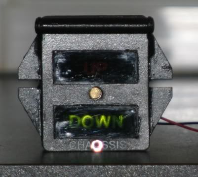
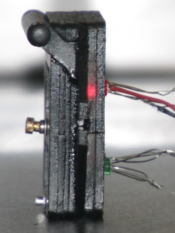
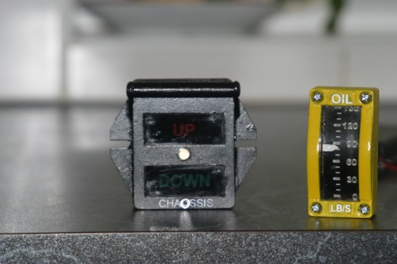
The Undercarriage Indicator is now finished thanks to Chris and his laser cutter and some heavy duty scratch building to finish it off. It is made of several layers of 3mm acrylic each with a different detail etched into it LED holder, legend, darkening panel, reflectors, mounting panel, top panel with Chassis and spacers.
The legend is engraved into the front face of two clear pieces, painted black before engraving and separated by a painted edge to prevent light bleed. A clear panel was then placed over this to give depth and make the writing just visible when not lit. (as per original).
The Night Shade holder is made from pine rod, with laser cut frames and end caps from power point screw cover tabs. I elected not to try to engrave the For night use label into this or stick one on the outside I may reconsider.
The clip for the nighthshade (bottom) was made out of a 3mm rivet with the rod removed and edges ground to a "nut" look and the case thumbscrew (centre) was made out of "bits" from old instruments

The real thing.

Oil Pressure Gauge
Again, laser cut in layers to allow a 3d effect. The hard part was putting this one together. The inside needed to be curved as it is a drum type instrument. The needle is scratch built from aluminium and fits into a slot lasered in the back plate.
The scale is laserlite which had to be bent onto the curved interior and stuck in place with no creases not fun. The needle floats above this by 1/2mm and then a sheet of clear had to be heated and bent to the curve (over a stainless steel coffee plunger!!), then mounted and glued keeping it above the needle and fitting in below either end of the face cut out. Again, a slow careful job and I had three spare windows. Luckily I managed to nail it with the first one.
This one is non functioning due to the drum arrangement being impractical for the sim cards. Above it on the panel will be a dual needle Fuel and Oil pressure gauge.
Finished product:

Real Gauge

Two that were always going to be difficult to manufacture but the original U/C indicators are about A$2500 and the original Oil Pressures are radioactive.
The third is completely scratch built (I thought Chris and his laser had already performed above and beyond) from an old helicopter oil pressure gauge. It is the Ammetre and came up quite nicely.
The face is actually a picture, photo-shopped to remove the needle then printed out on paper AND a reverse image on transperancy. These two were stuck together with clear glue and then fitted to the old face. This worked really well and makes it look much less like a picture and much more like a real face. Im going to use it for all the gauges I scratch build in the future.
The original OP gauge had a round face, which the ammeter doesnt, so I cut a front plate out of 1mm aluminium and shaped it to fit into the round raised bezel and cover the bottom third to match the original as closely as possible. The needle was fabricated from some plastic screw packet offcuts and a spacer put in to mount it on so it is 3d as well. The actual inside workings visible under the base of the needle came out particularly well but are just part of the picture.
Finished product.


Original instrument (but with needle removed from photo)

Im not unhappy with the final results and it keeps me busy until I can finish cutting the mount holes for these and the indicator lights and get the damned panel painted and assembled!

Darryl"Tony"
In memory of Flt Lt Tony Hill who, on 5 December 1941, at the request of Doctor R V Jones, successfully photographed a small "Würzburg radar" at Bruneval on the French coast. This from a height of only 200 ft, at high speed, under fire and from a camera mounted obliquely behind the cockpit.
-
10-08-2009, 09:41 PM #8675+ Posting Member

- Join Date
- Jun 2008
- Location
- Kelowna, British Columbia
- Posts
- 131
Re: Spitfire IX Project
Looks amazing as always. I havn't touched my own since the spring...been too busy, but starting up again.
Question regarding the yoke assembly and specifically the gas shocks for resistance. I'm using a similar set up, but I'm wondering with the yoke in the neutral position, are the shocks half compressed?
Through my own thinking on the problem they would have to be in order to allow travel on the opposite shock when say you pull all the way back on the stick. I'll be testing it in the next few days with my own, but I'm curious how this was solved.
The only other solution to this I was thinking of is to allow the opposing shock ie. the opposite shock as opposed to the direction you are pulling the stick, to slide on a rail in the direction you are pulling then when moving forward lets say, it would hit a stop then start compressing.
Also, what size are the shocks and how much travel do they have on them and how many pounds do you have to exert to compress. Thanks.
-
10-15-2009, 12:32 AM #87150+ Forum Groupie
- Join Date
- Jun 2008
- Location
- South West, Western Australia
- Posts
- 245
Re: Spitfire IX Project
 Originally Posted by Crescent

Thanks mate,
I'll have to let Gwyn answer most of your questions mate but I do know that the travel is only 11deg forward and 11 deg back so the stick does not move a huge way.
I think the forward shock actually "pulls" on the stick as you move the stick back and the rear when pushed forward. But it is a few moths since I have seen the unit.
Darryl"Tony"
In memory of Flt Lt Tony Hill who, on 5 December 1941, at the request of Doctor R V Jones, successfully photographed a small "Würzburg radar" at Bruneval on the French coast. This from a height of only 200 ft, at high speed, under fire and from a camera mounted obliquely behind the cockpit.
-
11-16-2009, 03:49 AM #88150+ Forum Groupie
- Join Date
- Jun 2008
- Location
- South West, Western Australia
- Posts
- 245
Re: Spitfire IX Project
At long last (and with the arrival of the clock) I have had a chance to cut the last of the instrument cutouts and finish off the panel.
With every new hole I got more nervous about *^&&(*&* up the next one and having to do the whole panel again but got there in the end.
Here is the raw panel ready for painting:

The spray painting went OK, but spray cans are not as reliable as they could be so the finish is not perfect..but good enough for a rushed wartime factory job I think.
I let it dry for twenty four hours and then fitted all the instruments, switches and additions.
I am very pleased with the results but the nightime photos with flash wash out the panel and really don't do it justice. I'll try to get some better ones soon.
Next I will finish fitting the controls to the shell and build the seat over the next couple of weeks. Not a bad weekend's work!!


I will have to take some more photos in daylight, the flash really does not do justice to the panel!!"Tony"
In memory of Flt Lt Tony Hill who, on 5 December 1941, at the request of Doctor R V Jones, successfully photographed a small "Würzburg radar" at Bruneval on the French coast. This from a height of only 200 ft, at high speed, under fire and from a camera mounted obliquely behind the cockpit.
-
Post Thanks / Like - 1 Thanks, 0 Likes, 0 Dislikes
Joe Cygan thanked for this post
-
11-16-2009, 03:57 AM #89MyCockpit Support Staff
- Join Date
- Nov 2005
- Location
- Perth, Western Australia
- Posts
- 1,415
Re: Spitfire IX Project
Explanation coming tomorrow, no time today!!! Gwyn
Originally Posted by Crescent
737NG using Prosim737, Immersive Calibration Pro, Aerosim Solutions motorized TQ & cockpit hardware, CP Flight MCP & FDS SYS1X, SYS2X & SYS4X, FDS PRO FMCs, AFDS units & Glarewings, Matrix Orbital ELEC display, Pokeys Landing & Cruise alt display, Buttkicker Gamers, 3 x BenqMW811ST projectors with a Matrox Th2Go
http://www.aerosimsolutions.com.au
Supporter of MyCockpit.org, please join me in donating!!!
-
11-16-2009, 08:10 AM #90150+ Forum Groupie
- Join Date
- Jun 2008
- Location
- South West, Western Australia
- Posts
- 245
Re: Spitfire IX Project
Ok,
Couldn't leave it alone, some more progress in a short time tonight.
The updated photos in better light conditions:


The Trim unit I built (with a real P51 Rudder Trim and Gwyn's fabricated Trim wheel), the two switches at the bottom are for Camera Power and Pitot Heat. The "tracks" are to run the chains back from the Elevator Trim wheel to a dummy set of push/pull rods.
Next to it is Gwyn's shameless attempt at making me look REALLY bad..his beautiful throttle Unit!

"The Office"
The real thing:


The sim so far


My favourite shot of the whole thing so far...the view from the throne:

I am actually starting to think I may finish this......
Darryl"Tony"
In memory of Flt Lt Tony Hill who, on 5 December 1941, at the request of Doctor R V Jones, successfully photographed a small "Würzburg radar" at Bruneval on the French coast. This from a height of only 200 ft, at high speed, under fire and from a camera mounted obliquely behind the cockpit.
-
Post Thanks / Like - 1 Thanks, 0 Likes, 0 Dislikes
Joe Cygan thanked for this post

 Reply With Quote
Similar Threads
-
Spitfire IX circa 1943
By graemesmith in forum Welcome to MyCockpit New here? Introduce Yourself!Replies: 2Last Post: 05-30-2010, 07:26 AM


Candid connections: Platform for casual relationships Live Women Prime Сasual Dating
Super Сasual Dating - Genuine...