

 Section
 Categories

Understanding Rotary Encoders
Rotary encoders are rotary switching devices used for changing things like radio frequencies, DG headings, and altimeter settings. For all its versatility this is a modest device having only two internal switches, each with minimal electrical capacity. The role of an encoder is simply to inform circuitry when a control knob has been turned and in which direction. It needs only enough capacity to switch logic signals. All the details of controlling radio frequencies, altimeter and heading settings are left to other bits of circuitry or firmware.
When the encoder shaft is turned, both switches open and close, spending the same amount of time open as closed; however they operate at slightly different times.
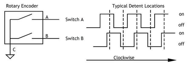
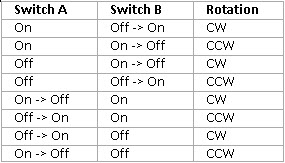
Only one switch changes state (opens or closes) at any one time. By knowing both if a switch opened or closed, and if the other switch is open or closed, logic circuitry or firmware in a micro controller can determine which direction the encoder shaft turned. By keeping track of how many switch openings and closures occur, circuitry/firmware can keep track of how far the shaft rotates.
If you take a look through the catalogs youll find a wide range of rotary encoders. The type described here (which is what we generally use in sim building) is referred to either as a quadrature incremental encoder or a 2-bit Gray encoder.
Take a look back at the encoder switching waveforms. Theyre a pair of square waves shifted one quarter of a cycle relative to each other. That quarter cycle shift is why the term quadrature is used.
Incremental means the switch outputs dont indicate the absolute rotational position of the shaft. They only signal that the position has changed a certain amount from a previous position.
A Gray code is a binary numbering sequence that allows only a single bit to change at a time. The familiar binary-weighted sequence we most frequently use has no such restriction on bits changing. Counting from 0 to 3 we have (00, 01, 10, 11). The transition from 01 to 10 requires that both bits change at the same time. Unfortunately, in the physical world its rare that we can get things to reliably change simultaneously. If we made a rotary encoder that followed a 2-bit binary-weighted sequence, the 01 to 10 transition would actually be (01, 00, 10) or (01, 11, 10) depending on which bit flipped first. The extra state would be short, but it would be there long enough confuse the electronics connected to the encoder. Frank Gray created a binary code that resolved this issue by only allowing a single bit to change at a time. The 2-bit Gray code sequence is (00, 01, 11, 10).
Rotary encoders are available in many different models with an assortment of options. Here are a few of the common options to specify when choosing a rotary encoder:
Switch type. The switching elements used in a rotary encoder are generally either mechanical or optical. The mechanical types are commonly used in consumer gear. The more reliable, and much more expensive, optical types are used in aerospace applications. Home cockpit applications usually call for mechanical switches.
Shaft Size. Choose the shaft diameter to match the knob youre using.
Terminal Type. This is the electrical connection. It might be pins for soldering into a circuit board, or tabs for connecting a wire.
Pulses per Revolution. An encoder will step through several Gray code sequences as it is turned through a complete revolution. Each (00, 01, 11, 10) sequence corresponds to a pulse. The more pulses per revolution, the smaller the angle you need to turn the shaft to make a change in the switch state. Eight PPR is common. You should consider the options for detents when you choose pulses per revolution.
Detents. Rotary encoders often have spring-loaded detents that hold the shaft at indexed locations through its rotation. As you rotate the shaft you can feel it click from one detent to the next. Depending on the encoder model there may be one, two, or four detents per pulse (or Gray code sequence). The correct number will depend on the specific application. Ideally, each detent should correspond with one step in whatevers being changed. What you want to avoid is having two or more change steps per detent. Two detents per pulse is common, but its best to check with the application/interface designer.
Push Switch. Incorporating a momentary push switch is a useful option. It lets you turn the shaft to adjust something like standby radio frequency then push the knob to swap the standby and active frequency settings.
Dual Encoders. A dual concentric rotary encoder works well for simulating avionics gear like radios which use concentric rotary controls. One rotary encoder is mounted behind another on a common axis. The front encoder has a hollow shaft. The rear encoder has a smaller, solid shaft that passes through it. There are separate knobs for the two shafts. The ELMA E37 series is an example. (See the ELMA spec sheet on Leo Bodnars website.)
Rotary encoders are made by many switch manufacturers and are available through most electronic component suppliers. You can also buy some of the common models used by flight sim hobbyists from Flightdeck Solutions and Leo Bodnar. (www.flightdecksolutions.com, www.leobodnar.com)
Mike Powell, author of
Building Recreational Flight Simulators and
Building Simulated Aircraft Instrumentation.
www.mikesflightdeckbooks.com